Instructions and Operating Manual SERIES X55-600 I TO P TRANSDUCERS
TABLE OF CONTENTS 1.0 General Description . . . . . . . . . . . . . . . . . . . . . . . . . . . . . . . . . . . . . . . . . . . . . . . .1 2.0 Specifications . . . . . . . . . . . . . . . . . . . . . . . . . . . . . . . . . . . . . . . . . . . . . . . . . . . . . . .1 3.0 Installation . . . . . . . . . . . . . . . . . . . . . . . . . . . . . . . . . . . . . . . . . . . . . . . . . . . . . . . . . .2 3.1 Electrical Connections . . . . . . . . . . . . . . . . . . . . . . . . . . . . . . . . . . . . .
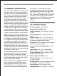
1.0 GENERAL DESCRIPTION The Ronan Model X55-600 I to P Transducer accepts a 4-20 or 10-50 mA control signal input and provides a regulated pressure output. The input current range is selectable by a switch located on the top of the module. The input pressure may be in the range of 20 to 120 psig and at least 5 psig above the maximum output pressure. The Model X55600 utilizes solid-state technology and output pressure sensing to provide a high degree of accuracy.
Temperature Drift: 0.01% of span per °F from 30 to 150°F (.025% below 30°F). Feed Flow (Output) Capacity: 3.0 SCFM at 20 psi supply, 10.5 SCFM at 100 psi supply. Bleed Flow (Exhaust) Capacity: 3 SCFM (20 SCFM optional). Pneumatic Connections: 1/4" MPT Electrical Connection: Screw compression (#30 to #16 awg. wire). Weight, Sizes & Ratings: Model Rating Weight Size(in.) X55-600-GP General Purpose 1.5 lbs. 3x2x5.2" X55-600-N4 NEMA4 1.75 lbs. 3.8x2.3x6.8" X55-600-Ex Exp. Proof 3.0 lbs. 4x4x5.4" 3.
3.3 Manifold Mounted Models The manifold mounted transducers share a single 3/8-18 NPT female inlet while having individual 1/4-18 NPT female outlet fittings. A dry, clean and filtered air supply is necessary for operation of the I to P transducers. It is not necessary to use all of the positions in a manifold chassis as each position is equipped with manual shutoff valves. of 4-12 mA or 12-20 mA input.
5.0 CALIBRATION Should calibration be required, use the following procedure. NOTE: if one of the front panel switches is changed to a new position, the calibration procedure will need to be performed. A clockwise rotation of the ZERO or SPAN control will result in an increase in the pressure output. 2. Ensure that there are no air leaks at all fittings. 3. Check the zero and span per Section 5 (Calibration). 4. Check to see if the input filter is obstructed (seated in the air input fitting).
.0 SETTING THE OUTPUT FOR LOSS OF POWER Ronan Model X55-600 I/P's are factory calibrated to drop below 3 psi upon loss of power (i.e. 0 mA). If for any reason this does not occur, or if you want the unit to drive upscale on loss of power, please follow the procedure below: 1. Connect a mA current calibrator to the I/P ± input terminals and a pneumatic measurement device to the I/P output. 2. With the air supply on, cycle the unit up/down (4/20 mA) a couple times.
eventually cause corrosion damage to the I/P. Input Terminals –+G Coalescing filters is an inexpensive way to help prevent I/P malfunctions or failures. These filters remove particles and moisture from air lines. 2) Oil in the supply air usually is from the main compressor. Oil can clog the small nozzles and disturb the normal operation of the I/P-converter. The result is poor control or in the worst case, failure. 3) Particles in the air usually occur because of corrosion.
8.
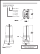
ORDERING INFORMATION X55-600 - GP - ( ) - SM Surface Mount Output Range 1 = 3-15 psig 2 = 3-27 psig 3 = 6-30 psig General Purpose ! OUTLINE DRAWING GENERAL PURPOSE SURFACE MOUNT TRANSDUCER (4) 8-32 cap screws supplied loose.
ORDERING INFORMATION X55-600 - GP - ( X55-600 )-M Manifold Mount Output Range 1 = 3-15 psig 2 = 3-27 psig 3 = 6-30 psig General Purpose 6-32 Captive Screw OUTLINE DRAWING GENERAL PURPOSE MANIFOLD MOUNT TRANSDUCER 9
ORDERING INFORMATION X55-600 - EX - ( ) - SM Surface Mount Output Range 1 = 3-15 psig 2 = 3-27 psig 3 = 6-30 psig Explosion Proof ! (4) 8-32 cap screws supplied loose.
ORDERING INFORMATION X55-600 - N4 - ( ) - DIN DIN Rail Mount Output Range 1 = 3-15 psig 2 = 3-27 psig 3 = 6-30 psig NEMA 4 Weather Proof 1/2 NPT 6.81 IN. (172,97 mm) 1/4 NPT DIN Rail 2.40 IN. (60,96 mm) 2.27 IN. (57,66 mm) 4.05 IN.
ORDERING INFORMATION X55-600 - N4 - ( ) - SM Surface Mount Output Range 1 = 3-15 psig 2 = 3-27 psig 3 = 6-30 psig NEMA 4 Weather Proof ! OUTLINE DRAWING NEMA 4 SURFACE MOUNT TRANSDUCER (4) 8-32 cap screws supplied loose.
3.300 (83.62MM) .180 (4.57MM) ! 13 8 plcs Output air ! 2.000 (50.80MM) .650 (16.51MM) ! ! A B 6.955 (176.66MM) ) 10 Point Capacity 8 point Capacity 4 point Capacity OUTLINE DRAWING SURFACE MOUNT MANIFOLD 0.156 (03.
ORDERING INFORMATION X55-600 - GP - ( ) - DIN DIN Rail Mount Output Range 1 = 3-15 psig 2 = 3-27 psig 3 = 6-30 psig General Purpose OUTLINE DRAWING GENERAL PURPOSE 35MM DIN RAIL MOUNT TRANSDUCER 14
.344 (8.74MM) ! ! 3.468 (88.09MM) ! 15 ! ! X55-600 - RM - 8 ORDERING INFORMATION 19.000 (482.60MM) 18.312 (465.12MM) ! ! .234 (5.94MM) OUTLINE DRAWING RACK MOUNT-8 MANIFOLD ! 3.000 (76.20MM) 0.250 (06.35MM) ! ! SUPPLY AIR 7.065 (179.
ORDERING INFORMATION Filter Regulator = X55 - 77 - 4 Output Gauge = X55 - 0 - 30 Input Gauge = X55 - 0 - 60 (Input Gauge not shown) OUTLINE DRAWING PREREGULATOR & GAUGE ASSEMBLY 16
OUTLINE DRAWING 2" DIAMETER PIPE MOUNT BRACKET 17
OUTLINE DRAWING 2" DIAMETER PIPE MOUNT BRACKET 18
X55-600-UMB X55-600-UMB-SS (STAINLESS STEEL) MOUNTING BRACKET 19
Instructions and Operating Manual SERIES X55-600 I TO P TRANSDUCERS Addendum Effective March 2004 INSTALLATION IN HAZARDOUS ENVIRONMENTS The X55 I/P transducers are approved by independent testing agencies for installation in areas as marked on a particular X55-600 model's label and as indicated below. The X55-600's shall operate safely when installed and connected per installation instructions shown in section 3.0 of this manual and when operated within the parameters shown in specification section 2.
Category and Code Marking for Model X55-600-EX: Explosion Proof: CSA or Factory Mutual Class I, II, III; Division 1, Groups B, C, D, E, F, G Explosion Proof and Flame Proof: 0518 EEx ia IIC T4 (-20°C < Ta < +80°C) Sira 03ATEX1074X Li=0 Ci=0.002uF Ui=29.5V Ii=104mA Pi=0.767W II 1G When used in explosive atmospheres, the X55-600-EX installation must be per local agency building codes.
RONAN ENGINEERING COMPANY P.O. Box 1275 21200 Oxnard Street Woodland Hills California 91367 U.S.A. (818) 883-5211 FAX (818) 992-6435 X55-600 / Rev. 5 RONAN ENGINEERING LIMITED U.K. 1 Tilley Road Crowther Industrial Estate Washington, Tyne and Wear United Kingdom, NE38-OEA (191) 416-1689 FAX (191) 416-5856 RONAN ENGINEERING LIMITED 32 Bermondsey Road Toronto, Ontario Canada, M4B1Z5 (416) 752-0310 FAX (416) 752-8072 Printed in U.S.A.