Instructions and Operating Manual X96S LEVEL GAGE
Table of Contents OVERVIEW......................................................................................................................... 1 Advantages.................................................................... 1 Gamma's Advantages..................................................................................................................................................... 1 X96S Advantages................................................................................................
Input Menus ................................................................................................................................................................. 21 Calibration Menu............................................................. 21 Ref Constants Menu..................................................................................................................................................... 21 Calibrate Menu.....................................................................
X96-2004PL................................................................... X96-2007PL................................................................... X96-2008PL................................................................... X96-2009PL................................................................... 43 43 43 44 OPTIONS.......................................................................................................................... 45 X96S Mechanical Chassis Part Numbers.................
Overview The X96S is a family of measurement products that is intended to replace the current X96N and X99 product families. These products: • use nuclear measurement techniques, • support all features of the current X96N and X99 products, • support up to 32 scintillation or ionization detectors, • optional HART interface, • improved user interface options1, • more user functionality, and • more product flexibility.
Basic Concepts Communications The Ronan X96S Level gage provides both 4-20 mA current loop and HART communications. 4-20 MA For many years, the field communication standard for process automation equipment has been a 4-20 mA current loop signal. The current varies in proportion to the process variable being represented. In typical applications, a signal of 4mA will correspond to the lower limit (0%) of the calibrated range and 20mA will correspond to the upper limit (100%) of the calibrated range.
Configuration Variables The Ronan X96S Level gage has many configuration variables that are accessed through its menus.
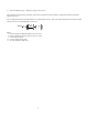
Theory Theory of Radiation Gaging Radiation gages operate on the principle of radiation absorption and transmission. A beam of gamma radiation is directed from the source holder, through the vessel and its process material, and onto the surface of the detector. Radiation which is not absorbed by the material through which it passes, is transmitted to the surface of the detector. Process measurement is possible because the amount of radiation absorbed and transmitted is predictable.
• Calibration (Referencing) – calibration of gage to user process. The Calibration (or Referencing) procedure relates detector output (in counts) to numeric values that accurately represent the actual process level. The level algorithm used by the X96S software is a simple transfer function.
Password Notice: To access the Programming Menu, the Password is 101010. Step 1: Power Up – You should now be on the Status Screen. Step 2: Press F3 to go back. Step 3: Now enter the password. (All digits are set at 000000 at this point.) Press to get the digit to be # one Press 2 times (The third digit should be highlighted.) Press to get the digit to be # one Press 2 times (The fifth digit should be highlighted.
Menus/Operation Menu Trees The Ronan X96S Level Gage uses a tree structured menu system.
Configuration Operation Level Config Head Temp Config Hardware HART System Operation Filtering Rad Disc Linearization Scan Time [ms] Level Config Units Low Range High Range Head Temp Config Temp Units Low Range High Range Hardware System Hardware Source Type HART Tag Name [name] MultiDrop [addr] Univ Rev [rev] Spec Rev [rev] System Serial # [number] Hardware Rev [rev] Software Rev [rev] Date [date] Hour (0-23) [hour] Minute [min] Date/Time Format [sel] Source Type Filtering Dyn Track [enable] Threshold
Figure 3-2 – Configuration Menus Digital Outputs Relay Relay Relay Relay TTL 1 TTL 2 TTL 3 TTL 4 1 2 3 4 Relay [number] Source [var] Alarm Type [type] Setpoint [value units] Setpoint2 [value units] Hysterisis [percent] Polarity [no/nc] TTL [number] Source [var] Alarm Type [type] Setpoint [value units] Setpoint2 [value units] Hysterisis [percent] Polarity [high/low] Digital Inputs Input Input Input Input Input Input Input Input 1 2 3 4 5 5 7 8 Input 1 Polarity [polarity] Type [type] Input 2 Polarity [po
Calibration State [state] Ref Constants Calibrate Ref Date [date] Loop Config Aux Loop Cfg Ref Constants Ref Mode [mode] Ref Time [time] MinRefCnts [counts] Calibrate Low Reference High Calibrate Clear Ref/Cal Loop Config Loop test Damping D/A trim Aux Loop Config Low Reference Reference Ref Level [value units] Ref Cap [counts] High Calibrate Calibrate Cal Level [value units] Cal Cap [counts] SV is [var] Loop test Damping D/A trim Figure 3-4 – Calibration Menus Root Menu The root menu is titled “Ronan
ITEM Variable Mapping PV SV TV QV Level Head Temp FUNCTION Selecting this choice takes the user to the Variable Mapping menu Shows the current value of PV (the Primary Variable) Shows the current value of SV (the Secondary Variable) Shows the current value of TV (the Third Variable) Shows the current value of QV (the Fourth Variable) Shows the current value of the Level Variable Shows the current value of Head Temp (the Head Temperature) Variable Mapping Menu The “Variable Mapping” menu allows the user to
ITEM Analog Bar Line 1: Line 2: Line 3: Line 4: Line 5: Line 6: Line 7: Line 8: FUNCTION Shows the current state of the analog bar display (enabled or disabled) and allows the user change the state.
ITEM Filtering Empty Clamp Detector Fault Linearization Scan Time FUNCTION Selecting this choice takes the user to the Filtering menu Selecting this choice takes the user to the Empty Clamp menu Selecting this choice takes the user to the Detector Fault menu Selecting this choice takes the user to the Linearization menu Shows the amount of time to accumulate each level sample and allows the user to change the time value.
Empty Clamp Menu The X96S uses a mechanism called empty clamp to protect detectors (particular scintillation detectors) from saturation conditions caused by the lack of process material to attenuate the radiation to the levels expected to be measured. The Min Counts and Max Counts parameters sets the threshold (in raw counts2) for activation of the empty clamp function.
ITEM Table Entry # Entry Used Measured Actual Set Entry Remove Entry FUNCTION Shows, and allows the user to select, an entry in the linearization table Shows if the entry is used or not. Shows, and allows the user to set, the measured value associated with this linearization table entry. This is a value calculated by the X96S. Shows, and allows the user to set, the actual value associated with this linearization table entry.
Alarms The Alarms menu is used to configure the parameters associated with the analog alarms.
ITEM CPU Card CPU Status DIO Card DIO Status Slot 3 Card Slot 3 Status Slot 4 Card Slot 4 Status Slot 5 Card Slot 5 Status Slot 6 Card Slot 6 Status Slot 7 Card Slot 7 Status Slot 8 Card Slot 8 Status Display Type Display Status HART HART Status FUNCTION Shows the type of CPU card installed (in slot 1) Status of the CPU card Shows the type of DIO (Digital Input/Output) card installed (in slot 2) Status of the DIO card Shows the type of card (if any) installed in slot 3 If a card is installed in slot 3, sho
ITEM Tag Name MultiDrop Univ Rev Spec Rev FUNCTION Shows, and allows the user to set, the device tag name Shows, and allows the user to set, the multi-drop address for a device (or 0 if the device is not used on a multi-drop loop) Shows the HART universal command revision to which this device is conformant Shows the HART specification revision to which this device is conformant System Menu The System menu is used to provide information about the X96S.
Relay Menus The Relay menus (Relay 1 through Relay 4) are used to configure the X96S relay outputs. These four relay menus show the settings of the corresponding relay output and allow the characteristics of the output to be changed.
ITEM Setpoint Setpoint2 Hysterisis Polarity FUNCTION Shows, and allows the user to set, Shows, and allows the user to set, Shows, and allows the user to set, Shows, and allows the user to set, the alarm set point the second alarm set point6 the alarm hysterisis percent the alarm polarity Alarm Source is one of the following: Alarm Source Level HeadTemp System Alarm Detector Flt Rad Disc Auto Cal Ref Auto Cal Err Not Used MEANING Operate this TTL output when Level is in alarm as defined by the Alarm Type
Input Menus The menu of each input (Input 1 through Input 8) contain the following items: ITEM Polarity Type FUNCTION Shows, and allows the user to set, the active state of the digital input Shows, and allows the user to set, the type of device connected to the the digital input Polarity is one of the following: Polarity Low High MEANING A “true” is represented by a low signal on the digital input A “true” is represented by a high signal on the digital input Type is one of the following: Type Manual Sen
ITEM Ref Mode Ref Time MinRefCnts FUNCTION Shows, and allows the user to set, the reference/calibrate mode Shows, and allows the user to set, the number of seconds of data to collect for a reference or calibrate sample Shows, and allows the user to set, the minimum raw value to use for a reference or calibrate sample Ref Mode is one of the following: Ref Mode Empty/Full Process Absorber MEANING Vessel will be Empty (air) for reference and Full (filled with process) for calibration in measuring area.
ITEM Loop test Damping D/A trim FUNCTION This item invokes a method that performs a test on the primary 4-20ma current loop Shows, and allows the user to set, the damping constant for the primary 4-20ma current loop This item invokes method that performs the D/A trimming of the primary 4-20ma current loop Aux Loop Cfg Menu This menu is used to access the secondary 4-20ma loop calibration procedures.
X96S Local Display X96S QQQQ 30% Ronan Engineering X96S Level Gage Menu Title Menu Menu Menu Menu Menu …. Menu line line line line line 1 2 3 4 5 line 11 Func1 F1 Func2 F2 Func3 F3 The X96S Local Display consists of a 16 line by 21 character display and a 10 key keypad. The top line of the display is reserved for the analog bar, if enabled. The next line is used for the Ronan logo. Line #3 shows the device model line. Line #4 displays the specific screen title.
Editing Values The editing of different types of values is designed around the use of the four direction keys and up to 4 function keys. The left and right arrow keys are used to position the cursor to the letter/digit to be edited, and up and down arrow keys are used to scroll between the possible values for this position. In all editing functions, the edited value is displayed below the current value.
Installation Caution Specific License General License Ronan's Monitor Systems use a sealed radioactive cesium (Cs-137) source which is safe if handled properly. Most Level Monitors are mounted to large vessels. Installations on vessels that permit personnel access require a specific license. Your company's specific license will name a Radiation Safety Officer (RSO) or Radiation Protection Officer (RPO). The RSO for your company must be notified immediately upon receipt of the gage.
Inspection The source holder is equipped with an ON/OFF mechanism. During shipment and storage the mechanism MUST BE SECURED in the OFF position with a padlock. Radiation Label If the padlock is damaged, broken, or missing, contact the RSO immediately.
Safety Precautions During installation the RSO will provide guidelines to assure safety. Consider the information presented in the Regulation/Safety Chapter of this manual, as well as the following general guidelines: The source holder must remain padlocked in the OFF position until installation is complete. Take all necessary precautions to assure that the source holder is not dropped or damaged.
Mechanical Mounting Review the Configuration Drawing which is included in the Drawing Chapter of this manual. Please reference the dimensional drawings located in he Drawing Chapter of this manual when installing the equipment. Drawings Consider the following general guidelines when mounting the sensor and detector: Avoid internal vessel obstructions such as baffles, agitators, manways, heater/cooler tubes, etc.
Electrical Installation of Interconnect Wiring DO NOT APPLY POWER until wiring is carefully checked. Drawings Drawings: Interconnect Wire the equipment according to the detailed interconnect drawing which is included in the Drawing Chapter of this manual. Follow local and national electrical codes for all interconnections.
Microprocessor Verification Rotate latch clockwise to open the enclosure door. Next remove the computer front cover by sliding the black tabs down. Check each board to see if they are fully seated into the mother board . Identify the CPU and other major boards from the drawing below. Optional configurations are possible. SERIAL PORT 1 SERIAL PORT 2 Power Supply Board REMOTE LCD Optional Board LCD Optional Board ION or Scint Board FUSE NOTE: These boards are not interchangeable in the frame’s slots.
Power-up X96S Ronan Engineering Please, wait…. Before applying power, ensure all boards are fully seated in frame’s slots. Close front door of the X96S and secure the door... When power is applied the X96S runs a self-diagnostic program First display appears for just a second F1 F3 F2 F4 C X96S Ronan Engineering X96S Density Gauge Ronan X96S – Density Variables Displays Configuration Digital Outputs Digital Inputs Calibration F1 F2 F3 The main display appears next as shown.
Password Notice: To access the Programming Menu, the Password is 101010. Step 1: Power Up – You should now be on the Status Screen. Step 2: Press F3 to go back. Step 3: Now enter the password. (All digits are set at 000000 at this point.) Press to get the digit to be # one Press 2 times (The third digit should be highlighted.) Press to get the digit to be # one Press 2 times (The fifth digit should be highlighted.
Calibration Calibration correlates the X96S's output to your actual process level. It instructs the microprocessor to read and store the detector counts for a low and high level of process. Once the system is conditioned to recognize the low and high level, it will provide a 4-20 mA output over the entire range of interest. Reference Modes One of your first tasks will be to calibrate the system. The first step in the calibration procedure is to "reference" the gage on some known level.
Configuration Ronan ships the Level Monitor System with factory-default software settings. Those settings are responsible for the information that initially appears on the status displays. After installation at your site, you may need to reconfigure the system to fit your application. The goal is to correlate the X96S output with your actual level readings.
Detector Scintillator Detector Description The Ronan scintillation detector consists of three main components: The plastic scintillation n crystal, the photomultiplier tube (PMT), and the associated electronics. Scintillation Crystal The crystal used for the Continuous Level Monitor System is poly vinyl toluene (PVT) plastic. The crystal produces light pulses which are proportional to the incident radiation events striking it.
Detector Service The critical components of the electronic circuit and the PMT/Crystal Assembly are aligned before leaving the factory. If any component of the Scintillation Detector is adjusted or replaced, the performance of the entire system will be adversely affected and will require realignment before continued use is possible. Therefore, the scintillation detector IS NOT field serviceable.
ION Chamber Detector/Amplifier Assembly (DET-7471-XXX) Ronan’s ion chamber detector is filled with an inert high-pressure gas. It uses low-voltage (-15VDC) bias and generates a low-level current proportional to the gamma radiation incident on the detector. The current generated is on the order of 10 ρA, so an electrometer amplifier is required to convert the current to a low-impedance, high level voltage signal.
Servicing the Detector The ion-chamber detector contains pressurized inert gas. The ion chamber itself is not serviceable and must be returned to the factory for service. Instructions follow for “Detector Removal/Replacement.” However, a qualified technician can troubleshoot and service the detector’s amplifier assembly. Instructions follow for that procedure as well. Some precautions are needed when handling the detector/amplifier assembly.
Detector Removal/ Replacement 1) Check NOTES below for illustrations and cautions that apply to your specific equipment. 2) Unscrew cap on detector housing. 3) Unscrew connector on top of detector. 4) Remove detector from housing. 5) Carefully install replacement detector in housing. 6) Screw connector back onto detector.
Removing the Detector Amplifier Circuit Board (CBAY-6102) Follow this procedure to remove the electrometer amplifier circuit board: 1. Remove the amplifier cover by unscrewing the hex socket head cap screws. 2. Remove the MS connector from the amplifier cover. 3. Remove the two 6-32 binding head screws, which secure the amplifier board to the detector. 4. Using a low power (60W) iron unsolder the detector leads to the printed circuit board standoffs.
Replacing the Detector Circuit Board/Connector Assembly Reference: B-6102-K If installing a new electrometer amplifier board, refer to drawing B-6102-K for internal connector wiring and connections to the detectors. Be sure the detector leads are straightened to clear the holes in the new circuit board. Follow this procedure. CAUTION: Excessive twisting or bending can damage the detector leads. 1. Carefully straighten the detector leads to clear the holes in the new circuit board. 2.
Electronics X96CPUDH X96CPUDH is a CPU Module that comes preloaded with the HART Level Gage firmware. X96-2002PL X96-2002PL is the local Graphics L.C.D. Module. This optional module provides: • Graphic LCD • Keypad X96-2003PL X96-2003PL is the Ionization Chamber Interface Module.
• • quadrature encoder11, or pulse counter. 4 relay (2 Amp capacity) output points are provided. Form “C” outputs are brought out to the connector (three connections per relay). 4 isolated open collector output points are provided. These outputs are capable of switching 4.5 to 30 Volts (externally supplied) at a maximum of 50 ma. 24 volts DC is provided to be used as a wetting voltage when needed. An isolated 15 volt DC power supply capable of providing 200 mA is also provided.
Options X96S Mechanical Chassis Part Numbers PART NUMBER DESCRIPTION X96S-N4-1 X96S-N4-2 X96S-SM-1 X96S-SM-2 X96S-PM-SD X96S-SRRD-1 X96S-SRRD-2 X96S-SRRD-3 X96S-SPD X96S NEMA 4 Enclosure, 6 Position, with Front Panel L.C.D. & Motherboard X96S NEMA 4 Enclosure, 9 Position, with Front Panel L.C.D. & Motherboard X96S Surface Mount, 6 Position, with Motherboard X96S Surface Mount, 9 Position, with Motherboard Panel Mount Serial Display Assembly Relay Rack Mount Serial L.C.D. Displays ONE L.C.D.
SPECIFICATIONS MODEL X96S Process Computer: Microprocessor-based unit wit a liquid crystal display, push-button interface, HART® Communications, process control outpus, process condition inputs, serial communications.
Regulations Regulations will be supplied with Radiation Safety Manual.
48 X96-N4-1 Outline Assembly Drawing 5.875 [149.21mm] 9.500 [241.30mm ] 11.500 [292.11mm ] 2.000 [50.80mm] 7.500 [190.50mm] 11.500 [292.10mm] 0.312 [07.
49 X96S-SM Outline/Assembly Drawing 10.340 [262.64mm] 8.000 [203.
Mounting Plate 50
51 X96S Terminal Arrangements
RONAN ENGINEERING COMPANY 21200 Oxnard Street Woodland Hills, California 91367 U.S.A. (800) 327-6626 • FAX (818) 992-6435 E-Mail: sales@ronan.com Web Site: http//www.ronan.com RONAN ENGINEERING COMPANY Measurements Division 8050 Production Drive Florence, Kentucky 41042 U.S.A. (859) 342-8500 • (859) 342-6426 E-mail: ronan@ronanmeasure.com Web Site: http//www.ronanmeasure.com X96S Level Gage Rev. 0.2 Printed in U.S.A.