Rondish UI DMS-02 v.
CONTENTS 1. EQUIPMENT DESCRIPTION 2. INSTALLATION 3. PROGRAMMING AND SETTING UP 4. SYSTEM OPERATION 5. TECHNICAL SPECIFICATIONS 6. DRAWINGS – INSTALLATION AND SETTING UP 6.1 INSTALLATION GUIDE (001/1 – 001/3) 6.2 ACTIVATING WRISTBAND (001/4) 6.3 QUICK PROGRAMMING GUIDE (001/5 – 001/6) 6.4 USE OF DOOR CONTACTS (001/7 – 001/8) 6.5 QUICK SET-UP FOR DOOR STRIPS 001/9 – 001/11) 7.1 FCC WARNING 7.2 CAUTION OF BATTERY REPLACEMENT 7.
1.0 EQUIPMENT DESCRIPTION 1.1 Rondish DMS-02 Strip Door Monitor This unit is a further upgrade of our successful DMS-01 door monitor. 1.1.1 Overview: Having some enhanced features, the two strip sensors are installed at each side of a door, or set up in an area and powered from a 12Vdc regulated supply. Power is connected to the free jack socket provided. These two sensing strips are cabled together and operate jointly to detect an approaching patient wearing a wristband transmitter.
Connections are provided for a 4 core telephone type cable for alarms and other signals to be routed to our central monitor. Connection of this cable at the central monitor is via our junction box (CMJ-01) and requires a 10K resistor to ground to ensure operation. (f) Wired reset option. Connections are provided at the bottom end of the sensor strips for a wired reset function e.g.
plastic strip monitor housing, the PCB inside can slide out of the housing, through the top, or bottom end to expose the various controls for adjustment. It is important to try to avoid placing the monitor immediately beside any metal objects, such as metal doors, electrical cables, metal cabinets etc as these can affect the performance of the door monitoring system.
When using two door monitor strips together on one door, it is necessary to program both units with the same door and area number but different door extension numbers. (Usually 1 & 2) (a) First set the required Door Identity Number (which particular door). Use a small screw driver to turn the rotary program switch (0 – 15 positions) and set desired Door Identity number. Observe that positions A = 10, B = 11, C = 12, D = 13, E = 14, F = 15.
In normal alarm operation, this “strip” monitor features an array of red LED lights inside the translucent cover. A number of LED’s are used to indicate “alarm on” (patient transmitter signal sensed - door contact open), one LED is used for “signal sensed”. - no alarm (door contact closed). Please refer to the Rondish Transmitter Programming Instruction Manual.
3.3.2 Checking performance Check the performance of the door monitor by carrying an active patient wristband transmitter and walking towards the door from a starting point, say 20ft from the sensors. As the door/area is approached, the wristband signals should be detected by the sensors at the approximate distance required from the door. If the distance is too great, or too small re-run the procedure with the set up transmitter as described above but you should note that settings are approximate only.
4.2 Normally closed door with pre-warning (see drawing 001/7) A magnetic door contact can be fitted. If a patient wearing a wristband enters the detection zone, the local sounder is activated (pre-alarm warning) and if fitted the door lock energized (refer to J11 option). While the door remains closed, the door monitor does not activate any main alarm.
(c) Ac mains adaptor (for regional ac voltage input): Regulated 12Vdc 500mA (UL/CE approved). 3) Magnetic door contact, or PIR connection: Uses “normally closed”, volt-free magnetic contact between the “Contact” and 0V terminals. 4) Maximum rating for relay output contacts: 1A (e.g. for door lock) 5) Adjustable buzzer volume (Internal) 6) Automatic “Out Of Range” and “Interference” detection with alert (used with Central Monitor) 7) Dimensions of housing: 720mm x 30mm x 20mm.
RONDISH STRIP DOOR MONITOR DMS-02 6. DRAWINGS – INSTALLATION AND SETTING UP 6.
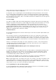
RONDISH STRIP DOOR MONITOR DMS-02 6.1 INSTALLATION GUIDE (001/1 – 001/3) Optional wired flashlight/sounder. Use +12V common.
RONDISH STRIP DOOR MONITOR DMS-02 6.1 INSTALLATION GUIDE (001/1 – 001/3) NOTE: Power, Lock and Magnertc Door Contact connections are duplicated at both ends of strip sensor units unit for convenience of connection.
6.
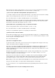
RONDISH STRIP DOOR MONITOR DMS-02 6.3 QUICK PROGRAMMING GUIDE (001/5 – 001/6) DOOR MONITOR STRIP : QUICK PROGRAMMING GUIDE Introducton: On the door strip monitor you can program the following items 1. Set door number on rotary switch 0-15(F) Identifies door number at Central Monitor NOTE: When two door monitor strips are used same door it should be set the same to allow to work together 2. Set area code/number on rotary switch 0-7 Must match the particular Central Monitor setting.
Rondish Door Monitoring System DMS-02 6.3 QUICK PROGRAMMING GUIDE (001/5 – 001/6) DOOR MONITOR QUICK PROGRAMMING PROCEDURE Step 3: (i) Press and hold programme mode button until you hear three(3) fast beeps. Set door number on rotary programming switch.(1-F) (ii) Press mode button until you hear one (1) "beep". Set area code number e.g. "0" will be received by any Central Monitor. (iii) Press and hold programme mode button until you hear two (2) beeps..
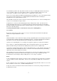
RONDISH STRIP DOOR MONITOR DMS-02 6.4 USE OF DOOR CONTACTS (001/7 – 001/8) USING DOOR CONTACTS, OR PIR TO AVOID FALSE ALARMS 1. Magnetic contacts NOTE: Due to the nature of electromagnetic signals and in operating wireless door monitoring systems, it should be noted that while a very high level of accuracy is achieved, 100% accuracy can not be guaranteed. Magnetic contact closed (door monitor disabled). Refer to J11 Door closed: pre-alarm sounds constant tone for preset time (e.g. 15 seconds).
Rondish Door Monitoring System DMS-02 6.4 USE OF DOOR CONTACTS (001/7 – 001/8) USING DOOR CONTACTS, OR PIR TO AVOID FALSE ALARMS Fitting a PIR detector can help reduce unwanted alarms in a close environment.
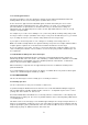
RONDISH STRIP DOOR MONITOR DMS-02 6.5 QUICK SET-UP FOR DOOR STRIPS 001/9 – 001/11) Strip Door Monitor quick setup procedure Introducton: Setting up the DMS-02 strip door monitor has been made easy using the TXP-02(LP) patient tansmitter for range test. NOTE: Do not press the program button on the monitor unit. Also, please note that maximum range of the unit (rotary switch at zero) is around 5-8 meters. You should first program the door strip monitors before setting up.
RONDISH STRIP DOOR MONITOR DMS-02 6.5 QUICK SET-UP FOR DOOR STRIPS 001/9 – 001/11) For setting up detection zone/range, please refer to User Instruction (Page 7 section 3.2) (a) start with door zone range rotary switch to a mid-way setting (7) (b) Using the range test transmitter, walk towards the door monitor (c) When the LEDs flash and a beep is heard, the monitor has detected the signal from the test transmitter.
RONDISH STRIP DOOR MONITOR DMS-02 6.5 QUICK SET-UP FOR DOOR STRIPS 001/9 – 001/11) DOOR STRIP QUICK SET-UP Rondish Patient Transmitter (TXP-02(LP)) (a) Switch on/activate a patient tracking wristband by refering to the User Instruction (Page 8 section 3.3.1) (b) Refer to USER INSTRUCTIONS section 3.0. Wearing a wristband on the wrist, test by walking towards the door/zone from different directions. If set correctly, the door monitor should alarm before you reach the door.
7.1 Warning: This device complies with Part 15 of the FCC Rules. Operation is subject to the following two conditions: (1) this device may not cause harmful interference, and (2) this device must accept any interference received, including interference that may cause undesired operation. NOTE: This equipment has been tested and found to comply with the limits for a Class B digital device, pursuant to Part 15 of the FCC Rules.