
User's Guide


6uA nom, 50mA max
Interrupt and Digital Interface Logic Levels: 1.8V to 3.3V CMOS
Digital Interface Output Drive Level: 2mA maximum
Audio Signal Level: 50mV minimum, 5V Maximum, AC coupled, 3KHz
nominal
RF Transceiver operation: 902-928MHz ISM Band
Protocol: proprietary but very similar to 802.15.4
Absolute Maximum Transmit power: 5.16 dBm
Control Signal Connector Type: Custom PCB Surface Mount pattern
Normal Operating Temperature Range: -0C to +40C
Operable Temperature Range: -20C to +60C
Maximum Humidity limit: 60C with 100% relative humidity for 24 hours
operating
Mechanical Vibration limit: Single axis sinusoidal for 4 hours,10-30-10Hz
sweeps at 2 cycles/min with 0.5 5mm displacement
Mechanical Shock limit: half sine, 109G@8.0mSec. Two shocks in all three
axes for a total of 12 shocks
o Available Interface Pins (requires Roost proprietary Schematic for identification)
Test Mode Enable (for Production line testing).
• Exerting TEST mode pin disables TRTN transmitter module
operation. Module will remain in standby mode (transmitter off) until
Roost proprietary Production line commands are sent across the
HOST UART DeBug port. Access to Roost Proprietery Production
Test Protocol is required for this mode of operation. But this Test
Mode operation is not offered to the HOST product manufacturer. See
Hardware Test Section 9 below for HOST product testing.
2 external interrupt pins to be connected to output of HOST sensor circuit.
These trigger the TRTN module Transmit condition which sends message to
Roost Hub.
HOST UART 2 wire DeBug port (requires Roost proprietary decoding
protocol)
5 General Logic Level, LED or Analog input/output drivers (source 10mA
max)
I2C Master (400kHz) for controlling external sensor chips.
4 wire SPI Master interface
2 wire JTAG interface for Firmware Programming Firmware.
VBAT power source input pin
4 ground pins.
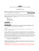
o Antenna is an integrated Johansson Chip Antenna (0900AT43A0070).
No external antenna is allowed to be used with this TRTN Transmitter
Module.
Sections 2 and 3 of this document outline user RF exposure information and
the HOST product user manual should also provide this same information
regarding RF exposure limits.
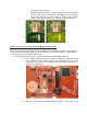
See below for proper ground plane pull back on HOST PCB.
• The last two pins on either side of the module adjacent to the antenna
area are Ground pins. The HOST PCB Ground plane should be