SUPER PRO GUN & SUPER PRO GUN II MAGNUM VENUS PRODUCTS Maintenance & Repair Manual Part No. M6707-1-1 Revision 04.14.
SUPER PRO GUN & SUPER PRO GUN II Maintenance & Repair Corporate HQ & Mfg. Phone: (727) 573-2955 Fax: (727) 571-3636 Email: info@magind.com Web: www.magind.com Manufacturing Phone: (253) 854-2660 (800) 448-6035 Fax: (253) 854-1666 Email: info@venusmagnum.com Web: www.venusmagnum.
Table of Contents SUPER PRO GUN & SUPER PRO GUN II Maintenance & Repair KNOW YOUR GUN Repair Kits in Detail for Super Pro Gun & Super Pro Gun II C H A P T E R 1 - ASSEMBLY INSTRUCTIONS Assembly Instructions for Super Pro Gun II Actuator C H A P T E R 2 - ASSEMBLY INSTRUCTIONS Assembly Instructions for Super Pro Gun II Handle C H A P T E R 3 - ASSEMBLY INSTRUCTIONS Assembly Instructions for Super Pro Gun II Block C H A P T E R 4 - ASSEMBLY INSTRUCTIONS Assembly Instructions for Super Pro SuperCutter C
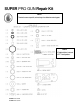
SUPER PRO GUN Repair Kit NOTE To order the correct repair kit, refer to the gun handle before ordering parts. NOTE ATurbulent Mixer is not used in FIT™ configurations.
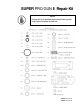
SUPER PRO GUN II Repair Kit NOTE The Super Pro Gun II is identified by either the blue handle or (on earlier versions)bythe#2stampedonthehandleside.
Chapter 1 SUPER PRO GUN Actuator Assembly 5106-01-01 See Figs. 9.1 & 9.2 for exploded schematic drawings 1. 2. 3. 4. Install the 7301-3-020 (O-Ring) onto the 5106-7-1 (Actuator Piston) and the two 5106-4-1 (Cylinder Caps) Using 6706-3-1 (Pro Gun Oil), lightly coat the Inside of the 5106-1-01 (Cylinder Body) and the 5106-7-1 (Actuator Piston). Install the 5106-5-1 (Actuator Bushing) into the 5106-7-1 (Actuator Piston).
NOTE The Piston should be inserted “bushing end first”, with the bushing on the top side of center. 5. 6. so 7. Install the two 5106-4-1 (Cylinder Caps). Place the 5106-2-1 (Actuator Seal) over the 5106-1-01 (Cylinder Body) the Mounting screw holes line up. Place the 5104-00-01 (Gun Block Assembly) onto the 5106-2-1 (Actuator Seal. NOTE The 5104-11-1 (Actuating Stem) must be inserted into the 5106-5-1 (Bushing) located in the 5106-7-1 (Actuating Piston). 8.
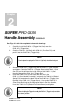
Chapter 2 SUPER PRO GUN Handle Assembly 5105-00-01 See Figs. 9.3 & 9.4 for exploded schematic drawings 1. 2. Carefully install the 5105-9-1 (Trigger Nut Seal) over the 5105-10-1 (Trigger Nut). Coat the 7304-4-1 (Lip Seal) with 6706-3-1 (Pro Gun Oil), and push it into the 5105-10-1 (Trigger Nut). NOTE Once in place the spring of the 7304-4-1 (Lip Seal) should be facing out. 3. 4. Screw the 5105-10-1 (Trigger Nut) into the 5105-1-1 (Gun Handle), and tighten.
5. 6. 7. 8. Set the 9203-2-1 (Compression Spring) into the spring seat located in the upper cavity of the 5105-1-1 (Gun Handle). Place the small pinhole in the 5105-3-1 (Slide Valve) over the pin through the 5105-14-1 (Trigger Stem), and push down compressing the spring into the handle cavity. Place the 5105-4-1 (Porting Plate Gasket) over the screws, matching the slot to the slot in the 5105-1-1 (Gun Handle).
NOTE Once in place the spring of the 7304-4-1 (Lip Seal) should be facing out. 3. 4. Screw the 5105-10-1 (Trigger Nut) into the 5110-7-1 (Gun Handle) and tighten. Coat the 5110-4-1 (trigger stem) with 6706-3-1 (Pro Gun Oil) and install from the inside cavity of the 5110-7-1 (Gun Handle) through the 5105-10-1 (trigger nut).
NOTE The slot in the side of the 5110-1-1 (Porting Plate) must line up with the slot in the 5110-7-1 (Gun Handle). 9. 10. 11. 12. 13. Set the 5105-6-1 (Toggle Washer) into the washer seal seat of the 5110-1-1 (Porting Plate) large side down.
Chapter 3 SUPER PRO GUN Gun Block Assembly 5104-00-01 See Figs. 9.9 - 9.12 for exploded schematic drawings Flush Valve Assembly 1. 2. 3. 4. 5. 6. 7. Install the 7301-11-008 (O-Ring) onto the 5104-25-1(Flush Valve Button). Install the 7301-3-007 (O-Ring) onto the 5104-23-1 (Flush Seal Body). Install the 9203-2-3 (Compression Spring) into the 5104-24-1 (Flush Valve Body). Smear 6706-2-1 (White Grease) onto the 5104-25-1 (Flush Valve Button), and the 5104-23-1 (Flush Seal Body).
Gun Block Assembly 1. 2. Check for and remove debris and burrs in 5104-1-1 (Gun Block). Install the two 5104-3-1 (Secondary Seals) in the 5104-1-1 (Gun Block). See Fig. 3.1 Fig. 3.1 3. 4. 5. 6. Install the 5104-10-1 (Center Spacer) into the center area of the 5104-1-1 (Gun Block). Insert the 9301-5-1 (Seal Installation Tool) through the side of the gun block to align the 5104-10-1 (Center Spacer) with the 5104-3-1 (Secondary Seals).
NOTE Before inserting the SealAlignment Tool, align the holes in the 5401-6-1 (Teflon Catalyst Seal) with the holes in the 5104-1-1 (Gun Block) as closely aspossible. 7. Press firmly, or tap with a hammer until the seal assembly bottoms out in the 5104-1-1 (Gun Block), then gently remove the Seal Installation Tool. 8. Hold the 9301-4-1 (Catalyst Seal Alignment Tool) firmly with a pair of pliers. 9.
Fig. 3.4 14. Press firmly, or tap with a hammer until the seal assembly bottoms out in the 5104-1-1 (Gun Block), then gently remove the Seal Alignment Tool. 15. Hold the 9301-4-2 (Resin Seal Alignment Tool) firmly with a pair of pliers. 16. Insert the tapered end of the 9301-4-2 (Resin Seal Alignment Tool), into the 5104-1-1 (Gun Block) through the resin fitting port on the back of the Gun Block. 17.
18. Install the 5104-2-1 (Valve Rod) through the resin side of the gun. Use the 9301-5-1 (Seal Installation Tool) to center the Valve Rod in the 5104-1-1 (Gun Block). NOTE Make sure that the Valve Rod is correctly aligned; the larger hole goes on the resin side, while the smaller hole goes on the catalyst side. See Fig. 3.6. NOTE The middle hole, into which the actuating stem will be inserted, must also be correctly aligned. One end of the hole has a relief in the threads, which shouldfacedown. SeeFig.3.6.
20. Install the 5104-11-1 (Actuating Stem) into the 5104-2-1 (Valve Rod). NOTE UseremovablestrengththreadlockingcompoundonActuatingStemthreads. 21. Actuate the 5104-11-1 (Valve Stem) back and forth 3 or 4 times, then snug both 5104-8-1 (Packing Nuts) with 9301-2-3 (Packing Bit) until firm. Again, actuate the Valve Stem back and forth 3 or 4 times. 22. Install the 5104-32-1 (Plug), and the 7301-15-125 (O-Ring) in the port provided on the catalyst side of the 5104-1-1 (Gun Block). 23.
27. Position the 5104-12-1 (Mix Housing Seal) onto the backside of the 5104-20-1 (Mix Housing). See Fig. 3.8. Fig. 3.8 28. Using the two 7102-1-6 (Socket Head Cap Screws), mount the 5104-20-1 (Mix Housing) onto the 5104-1-1 (Gun Block).
Chapter 4 SUPER PRO GUN SuperCutter Assembly 5101-01-01 See Figs. 9.13 - 9.20 for exploded schematic drawings NOTE ThesharpedgeoftheChopperBladesshouldbeslightlydulledbystropping them on cardboard prior to installation into RotorAssembly. This intentional dulling of the blades by the whetting process will avoid slicing and nicking of the Rubber Roll and will assure longer life of both Blades and Rubber Roll. SeeFig.4.1. Fig. 4.
Rotor Assembly 1. Insert 9210-1-1 (Chopper Blades) between the 5103-28-1 (Rotor Hub) and 5103-29-1 (Wedge Insert). The back edge of the Blade must be bottomed against the Rotor Hub. See Fig. 4.2. Fig. 4.2 2. 3. 4. Align the edges of the blade with the end of the 5103-28-1 (Rotor Hub). Tighten the 7102-13-6 (Socket Flat Head Screw) in the 5103-29-1 (Wedge Insert) to secure the blades in place. Wipe a small amount of grease on the 8402-1-1 (Air Motor) shaft.
Fig. 4.3 Rubber Roll Assembly 5. 6. Press the 5103-6-1 (Rubber Roll) onto the 5103-5-01 (Mandrel Assembly). Secure the Rubber Roll by inserting the 7205-3-31 (E-Ring) into the groove in the Mandrel. See Fig. 4.4. Insert the Mandrel/Rubber Roll Assembly into the top of the T-Slot on the 5103-1-1 (Base Plate). Align the 5103-4-1 (Slide Adjust Nut) with the T-Slot. See Fig. 4.5. Fig. 4.4 Fig. 4.
7. Slide Rubber Roll Assembly toward the 5103-03-01 (Wedge Rotor Assembly) and tighten the 7102-2-20 (Socket Head Cap Screw) Rubber Roll Adjustment 1. Slightly loosen the 7102-2-20 (Socket Head Cap Screw), just enough so the Rubber Roll Assembly will slide in the T-Slot. See Fig. 4.6. Fig. 4.6 2. Apply slight pressure of the Rubber Roll Assembly to the 5103-03-01 (Wedge Rotor Assembly), and tighten the 7102-2-20 (Socket Head Cap Screw).
Idler Adjustment 1. Slightly loosen the 7102-2-20 (Socket Head Cap Screw), just enough so the Idler Assembly will slide in the T-Slot. See Fig. 4.7. Fig. 4.7 2. Slide the 5103-7-01 (Sleeve w/ Bearing) until it just makes contact with the 5106-6-1 (Rubber Roll). NOTE Proper adjustment has Idler Assembly touching the Rubber Roll, but still able to rotate with minimum effort.
Chapter 5 SUPER PRO GUN Actuator Disassembly 5106-01-01 See Figs. 9.1 & 9.2 for exploded schematic drawings 1. Unscrew the two 5105-13-1 (Rear Screws), and the two 5105-12-1 (Front Screws) to remove the 5106-00-01 (Cylinder Body Assembly) from the 5105-00-01 (Gun Handle Assembly). 2. Remove the two 5106-4-1 (Cylinder Caps) from the 5106-1-1 (Cylinder Body). Remove and discard the two 7301-3-020 (O-Rings) from the 5106-4-1 (Cylinder Caps). 3.
Chapter 6 SUPER PRO GUN Handle Disassembly 5105-00-01 See Figs. 9.3 & 9.4 for exploded schematic drawings 1. Remove and discard the 5105-7-1 (Cylinder Gasket), and the 5105-6-1(Toggle Washer) from the 5105-5-1 (Porting Plate). 2. Remove the 5105-5-1 (Porting Plate) from the 5105-1-1 (Gun Handle). 3. Remove the 5105-4-1 (Porting Plate Gasket), 5105-3-1 (Slide Valve), and the 9203-2-1 (Compression Spring) from the 5105-1-1 (Gun Handle). Discard the Porting Plate Gasket and Compression Spring. 4.
7. Remove and discard the 5105-9-1 (Trigger Nut Seal), and the 7304-4-1 (Lip Seal) from the 5105-10-1 (Trigger Nut) NOTE Discard all parts to be replaced by repair kit. All remaining parts should be thoroughlycleaned,inspectedfordamage,andreplacedifnecessary. SUPER PRO GUN II Handle Disassembly 5110-7-1 See Figs. 9.5 & 9.6 for exploded schematic drawings 1. Remove and discard the 5110-6-1 (Cylinder Gasket), and the 5105-6-1(Toggle Washer) from the 5110-1-1 (Porting Plate). 2.
Chapter 7 SUPER PRO GUN Gun Block Disassembly 5104-00-01 See Figs. 9.9 - 9.12 for exploded schematic drawings 1. Remove the four 5106-6-1 (Mounting Screws), and the four 5106-3-1 (Mounting Seals) to remove the 5104-00-01 (Gun Block Assembly) from the 5106-00-01 (Gun Actuator Assembly). 2. Remove the two 7102-1-6 (Socket Head Cap Screws) to remove the 5104-20-1 (Mix Housing) from the Gun Block Assembly. 3.
13. Using the 9301-5-1 (Seal Installation Tool), force the Seal Assembly out of the Gun Block. NOTE SealAssemblyconsistsof;two5104-7-1(PackingRings),two5104-4-1 (ReliefSpacers),two5104-3-1(SecondarySeals),One5104-6-1(Teflon CatalystSeal),andone5104-5-1(TeflonResinSeal). Flush Valve Disassembly Procedures: 1. Remove and discard the 5104-21-1 (Flush Valve Split Seal) from the 5104-24-1 (Flush Valve Body). 2. Remove the 5104-02-01 (Flush Elbow Assembly) from 5104-22-1 (Flush Valve Neck). 3.
Chapter 8 SUPER PRO GUN SuperCutter Disassembly 5103-00-01 See Figs. 9.13 - 9.20 for exploded schematic drawings 1. Unscrew the 5103-14-1 (Cover Nut) and remove the 5103-13-1 (Chopper Cover) from the 5103-00-01 (Roving Cutter Basic Assembly). The remainder of the disassembly covered in this manual pertains to the rubber roll and the rotor. Rubber Roll Disassembly 2.
Rotor Disassembly 4. Loosen the two 7102-14-6 (Socket Cup Point Set Screws), and slide the 5103-03-01 (8-Blade Rotor Assembly) off of the 8402-1-1 (Air Motor) shaft. NOTE BeverycarefulwhenhandlingtheRotorAssemblyasthebladesaresharpand could cause injury. 5.
Chapter 9 SUPER PRO GUN & SUPER PRO GUN II Assembly Drawings 26 SUPER PRO GUN & SUPER PRO GUN II
Fig. 9.
Fig. 9.
Fig. 9.
Fig. 9.
Fig. 9.
Fig. 9.
Fig. 9.
Fig. 9.
Fig. 9.
Fig. 9.
Fig. 9.
Fig. 9.
Fig. 9.13 NOTE These wedge rotors will not fit on the old style “classic” pro gun choppers (58605-1). They are forSuperProandSuperProIIchopper configurations. Please use the following part numbers for rotors: 77730-1 (6 blade) or 77731-1 (8 blade).
Fig. 9.
Fig. 9.
Fig. 9.
Fig. 9.
Fig. 9.
Fig. 9.
Fig. 9.
Fig. 9.
Fig. 9.
SUPER PRO GUN & SUPER PRO GUN II
SUPER PRO GUN & SUPER PRO GUN II
Corporate HQ & Mfg. 5148 113th Ave. Clearwater, FL 33760 · USA Phone: (727) 573-2955 Fax: (727) 571-3636 Email: info@mvpind.com Manufacturing/Sales 1862 Ives Ave. Kent, WA 98032 · USA Phone: (253) 854-2660 (800) 448-6035 Fax: (253) 854-1666 · Web: www.mvpind.