ELECTRIC DRYER INSTALLATION INSTRUCTIONS 29" WIDE MODELS - U.S.A. ONLY Para obtener acceso al manual de uso y cuidado en espafiol, o para obtener informacién adicional acerca de su producto, visite: www.whirlpool.com Tenga listo su numero de modelo completo. Puede encontrar el numero de modelo y de serie dentro de la cavidad superior de la puerta. Table of Contents DRYER SAFETY 0. ..ccccccccceceeceeeceressenaeeeceeeeeeceesenenaeeeseaeeeeceenenenaaes 2 INSTALLATION REQUIREMENTS. ...0..
DRYER SAFETY Your safety and the safety of others are very important. We have provided many important safety messages in this manual and on your appliance. Always read and obey all safety messages. This is the safety alert symbol. This symbol alerts you to potential hazards that can kill or hurt you and others. All safety messages will follow the safety alert symbol and either the word “DANGER?” or “WARNING.
IMPORTANT SAFETY INSTRUCTIONS WARNING: To reduce the risk of fire, electric shock, or injury to persons when using the dryer, follow basic precautions, including the following: Read all instructions before using the dryer. Do not place items exposed to cooking oils in your dryer. Items contaminated with cooking oils may contribute to a chemical reaction that could cause a load to catch fire.
INSTALLATION REQUIREMENTS QQ ~~ Tools and Parts Gather the required tools and parts before starting installation. Read and follow the instructions provided with any tools listed here.
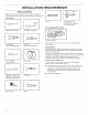
Minimum spacing for recessed area or closet installation Location Requirements The dimensions shown following are for the minimum spacing allowed. AWARNING Explosion Hazard @ Additional spacing should be considered for ease of installation and servicing. @ Additional clearances might be required for wall, door, and floor moldings. @ Additional spacing of 1" (25 mm) on all sides of the dryer is recommended to reduce noise transfer.
Electrical Requirements lf your outlet looks like this: O It is your responsibility: @ Tocontact a qualified electrical installer. @ To be sure that the electrical connection is adequate and in conformance with the National Electrical Code, ANSI/NFPA 70-latest edition and all local codes and ordinances. The National Electrical Code requires a 4-wire power supply connection for homes built after 1996, dryer circuits involved in remodeling after 1996, and all mobile home installations.
install Leveling Legs Electrical Connection A WARNING Power Supply Cord A WARNING Gh) é Excessive Weight Hazard Use two or more people to move and install dryer. Failure to do so can result in back or other injury. (4 » Prepare dryer for leveling legs Fire Hazard Use a new UL listed 30 amp power supply cord. Use a UL listed strain relief. Disconnect power before making electrical connections. Connect neutral wire (white or center wire) to center terminal (silver).
Power Supply Cord Connection Direct Wire A WARNING Power supply cord strain relief {— Gh 4, é Attach power supply cord strain relief Fire Hazard Use 10 gauge copper wire. Use a UL listed strain relief. Disconnect power before making electrical connections. Connect neutral wire (white or center wire) to center terminal (silver). Ground wire (green or bare wire) must be connected to green ground connector. Securely tighten all electrical connections.
4-wire Power Supply Cord Connection (5. Connect ground wire IMPORTANT: A 4-wire connection is required for mobile homes and where local codes do not permit the use of 3-wire connections. Cc D Qm7moows 4-wire receptacle (NEMA type 14-30R) 4-prong plug Ground prong . Neutral prong Spade terminals with upturned ends 3/4" (19 mm) UL listed strain relief Ring terminals (3. Prepare to connect neutral ground wire and neutral wire. Remove center terminal block screw (B).
(— 4. Connect . neutral wire (2. Attach direct wire cable to strain relief SON Connect neutral wire (white or center) (C) of power supply cord to center terminal block screw (B). Tighten screw. a . . 5, Connect remaining wires should have a tight fit with the dryer cabinet and be in a horizontal position. Tighten strain relief screws. For 3-wire Direct Wire Connection, see page 11. For 4 wire Direct Wire Connection, continue to step 3 below.
s (i (8. 5. Prepare to connect neutral ground wire and neutral wire r IG ~ Lacea — | alah al <8 ag|-|°S C eL : Connect remaining wires A ~ Vb ha B CG Remove center terminal block screw (B). Remove neutral ground wire (E) from external ground conductor screw (A). lL Place outer ends block down psn hooked ends of remaining direct wire cable wires under terminal block screws (hooks facing right). Squeeze hooked together and tighten screws.
6. Connect (a neutral wire . 2. Connect neutral ground wire and neutral wire a “u AN is ale BY center) (C) of direct or (B). Squeeze (white screw wire cable under center ral wire block utterminal end of neTighten okedtogether. ace hoend Pl hooked screw. ( _ . 7. Connect remaining wires Connect neutral ground wire (E) and neutral wire (white or center wire) (C) of power supply cord or cable under center terminal block screw (B). Tighten screw. ( _ . 3. Connect remaining wires fa a) .
VENTING Venting Requirements Exhaust hoods: @ 4 WARNING Gh) é Must be at least 12" (805 mm) from ground or any object that may obstruct exhaust (such as flowers, rocks, bushes, or snow). Recommended Styles: Fire Hazard Use a heavy metal vent. Louvered hood Do not use a plastic vent. Do not use a metal foil vent. Box hood Acceptable Style: Failure to follow these instructions can result in death or fire. WARNING: EXHAUSTED IMPORTANT: To reduce the risk of fire, this dryer MUST BE OUTDOORS.
Plan Vent System Recommended exhaust installations Alternate installations for close clearances Venting systerns come in many varieties. Select the type best for your installation. Two close-clearance installations are shown. Refer to the manufacturer’s instructions. Typical installations vent the dryer from the rear of the dryer. Other installations are possible. A-— NNN A. B. C. D. Dryer Elbow Wall Exhaust hood E. F. G. H.
Special provisions for mobile home installations: The exhaust vent must be securely fastened to a noncombustible portion of the mobile home structure and must not terminate beneath the mobile home. Terminate the exhaust vent outside. (— L Vent System Chart (Long Vent Models Only) Number of 90° turns or elbows Type of vent 0 Rigid metal 120 ft. (36.6 m) 1 Rigid metal 110 ft. (83.5 m) 2 Rigid metal 100 ft. (30.5 m) 3 Rigid metal 90 ft. (27.4 m) 4 Rigid metal 80 ft. (24.
NOTE: The dryer must be level for the moisture sensing system to operate correctly. Connect Vent 1. Connect vent to exhaust outlet T Ses th] a a jo a oo ETF EF Es —— Not Level (, LEVEL = = Not Level = 2. Tighten and adjust leveling legs I (“Wi Using a 4" (102 mm) clamp, connect vent to in dryer. If connecting to existing vent, make clean. Dryer vent must fit over dryer exhaust exhaust hood. Check that vent is secured to with a 4" (102 mm) clamp.
[-] When the dryer has been running for 5 minutes, open the dryer door and feel for heat. If you feel heat, cancel cycle and close the door. if you do not feel heat, turn off dryer, and check the following: @ There may be 2 the dryer. Check that both circuit no heat, contact household fuses or circuit breakers for that both fuses are intact and tight, or breakers have not tripped. If there is still a qualified technician. NOTE: You may notice an odor when the dryer is first heated.
( . {, 8. 6. Switch door catch, bezel, & plug Flip door over a Catch and bezel | Flip door over so handle side is down. f 9. Attach door hinges Remove the door catch, bezel, and plug from the inside of the inner door by squeezing and pulling/pushing them. Place the door catch, bezel, and plug on the sides opposite from where they were. (7. Rotate outer door Reattach outer door panel to inner door panel so handle is on the side where hinges were just removed. Insert 4 door screws.
(4 OQ. Remove = (a 12. door strike and door strike plug Door strike ae Insert screws in hinge holes on dryer cabinet Door strike plug e Remove door strike and door strike plug from dryer cabinet. Insert the door strike into door strike plug hole and secure with screw. Insert door strike plug into original door strike hole and secure with screw. 7 11. Remove and transfer hinge hole plugs NOTE: Two people may be needed to reinstall door.
W10514172A W10514174A-SP ®/™ ©2013 Whirlpool. All rights reserved. 01/13 Printed in U.S.A.