ULTRAMATRIX 4X, 8X, AND 16X INSTALLATION AND OPERATIONS MANUAL 10707 Stancliff Road Houston, Texas 77099 Phone: (281) 933-7673 WWW.ROSE.
LIMITED WARRANTY Rose Electronics warrants the UltraMatrix™ to be in good working order for one year from the date of purchase from Rose Electronics or an authorized dealer. Should this product fail to be in good working order at any time during this one-year warranty period, Rose Electronics will, at its option, repair or replace the Unit as set forth below. Repair parts and replacement units will be either reconditioned or new. All replaced parts become the property of Rose Electronics.
FCC/IC STATEMENTS, EU DECLARATION OF CONFORMITY FEDERAL COMMUNICATIONS COMMISSION AND INDUSTRY CANADA RADIO-FREQUENCY INTERFERENCE STATEMENTS This equipment generates, uses, and can radiate radio frequency energy and if not installed and used properly, that is, in strict accordance with the manufacturer’s instructions, may cause interference to radio communication.
TABLE OF CONTENTS Contents Disclaimer........................................................................................................................................................................ 1 About this manual ........................................................................................................................................................... 1 Introduction....................................................................................................................
Figures Figure 1. UltraMatrix models ........................................................................................................................................... 4 Figure 2. UM4 Expansion card........................................................................................................................................ 6 Figure 3. UM8 or UM16 Expansion card.........................................................................................................................
INTRODUCTION Disclaimer While every precaution has been taken in the preparation of this manual, the manufacturer assumes no responsibility for errors or omissions. Neither does the manufacturer assume any liability for damages resulting from the use of the information contained herein. The manufacturer reserves the right to change the specifications, functions, or circuitry of the product at any time without notice.
Features Upgradability Free lifetime base firmware upgrades, based on flash memory technology, provide new features and improvements. Base firmware upgrades are available from our web site at www.rose.com. Security Unique configuration password for persons authorized to perform configuration maintenance. User names and passwords allow controlled access to computers with sensitive information, system data, or restricted applications.
Cable requirements The cable requirements for your system will vary depending on the types of CPUs connected to the UltraMatrix switch and the equipment used for the KVM stations. A KVM adapter cable is needed for each KVM station, a CPU adapter cable is needed for each computer/server that is connected to the UltraMatrix, and if the units are connected in an expansion topology, expansion cables will be needed to connect the units together.
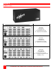
MODELS UltraMatrix models UltraMatrix – Rear panel Model number 4X model UM4-aXbU/E a = # users (0-4) b = # CPUs (4, 8, 12, 16) /E = expansion card installed 8X model UM8-aXbU/E a = # users (0-4) b = # CPUs (4, 8, 12, 16) /E = expansion card installed 16X model UM16-aXbU/Ec a = # users (0-4) b = # CPUs (4, 8, 12, 16) /Ec, c = number of expansion cards installed (1 or 2) Figure 1.
OVERVIEW System overview The UltraMatrix switch is designed with the latest in KVM switching technology. It has the capability and flexibility to configure to most keyboards, video monitors, mice, servers and computers. The modular design of the UltraMatrix makes the unit easy to install, expand, and maintain. The addition of an expansion card(s) and additional switches can increase the number of computers that can be accessed up to 1,000.
To expand the UltraMatrix switch in an expanded configuration, an expansion card must be installed in each UltraMatrix switch. Figure 2 shows the expansion card used for the “4X” model, Figure 3 shows the expansion card used for the 8X and 16X models. The 16X model has an upper and lower expansion card installed. Out 1 and In 1 connectors on the expansion card transmit and receive all keyboard, mouse and system signals and the video signals for KVM 1 and KVM 2.
OUT1 IN1 IN4 OUT4 OUT2 IN3 IN2 OUT3 IN3 OUT4 IN4 OUT3 IN2 OUT2 IN1 OUT1 JUMPER OFF-RING JP15 JUMPER ON-BUS KVM 1-4 KVM 5-8 KVM 9-12 KVM 13-16 UPPER CARD LOWER CARD JP2 JP1 UP DOWN JP1 & JP2 JUMPER SETTINGS UP DOWN Figure 3.
Jumpers JP1 and JP2 set the KVM assignments for the UM8 and UM16 models. On the UM8 model, setting jumpers JP1 and JP2 in the “DOWN” position sets the KVM ports for that Unit to KVM 1-4. In the “UP” position, the KVM ports are set to KVM 5-8. On the UM16 model, setting jumpers JP1 and JP2 to the “DOWN” position on the bottom expansion card sets the KVM ports to KVM 1-4. Setting JP1 and JP2 to the “UP” position on the bottom card sets the KVM ports to KVM 5-8.
SITE PLANNING Site planning Organizing your site and planning the placement of the computers, the KVM stations, the UltraMatrix switches, and the routing of the cables is a key part in the installation and configuration process. Care should be taken when connecting the computers, KVMs, and the UltraMatrix switches. Locate the UltraMatrix as close as possible to the computers so the cables are as short as possible but still give some freedom of movement.
INSTALLATION Switch installation – Single unit PLEASE REFER TO THE SAFETY SECTION BEFORE INSTALLATION The basic installation of a single UltraMatrix switch is an easy and straightforward procedure. To install a single switch, perform the below steps for all computers/servers that will be connected. It is recommended that all computers and servers be powered off.
Perform the following installation steps for each computer/server that will be connected to the UltraMatrix. Sequentially connect the computers/servers starting with computer #1. (Refer to Figure 4) Refer to the troubleshooting section for help if needed. NOTE: When entering information into the UltraMatrix menu system, use the numeric keys above the keyboard for entering numbers. The numeric keypad cannot be used for entering information into the menu system.
Multi-switch installation – General The UltraMatrix switch can be installed in a variety of expanded topologies. The BUS, RING, Split BUS, and Staggered BUS are the most common configurations. In any expanded system, each expansion port pair (Out1/ IN1) on an expansion card carry the video information for two KVM stations (See Table 1 and Table 2).
Steps: 1. Connect a KVM station to Unit #1’s KVM #1 port. Turn on the KVM monitor and Unit #1. (Wait for the internal diagnostic check is complete) 2. Call-up the “Main” menu by pressing and releasing the left control [Ctrl] key, then the F12 key. 3. From the “Main” menu, select “Status” and press [Enter]. The system “Status” display will appear. The “Status” display shows the following information. (See Figure 25) a. Computers b. Power (Power on status) c. POS (Card position) d. VER (Program version) e.
When all computers are connected to the UltraMatrix switches and functioning properly, the basic BUS installation is complete. KVM stations connected to Unit #1 can switch to any computer in the system. Other configuration parameters can be set-up for the system, computers, KVM stations, users, profiles, groups, and languages. See the “Configuration menu” section and the Operations section for using the UltraMatrix switch.
Multi-switch installation – RING topology Refer to Figure 8 for a typical RING topology for the UM4 model, Figure 9 for the UM8 model, and Figure 10 for the UM16 model. The “RING” installation procedure is very similar to installing a “BUS” configuration with the exception of removing jumper JP3 on the expansion cards on two UM4 Units or jumper JP15 on two UM8/UM16 Units and adding expansion cables from the first Unit to the last Unit.
10. 11. Switch the KVM station to the next sequential CPU port as explained in step 6 and perform steps 7 – 9 for this computer and for the remaining computers. Connect other KVM stations as needed to the UltraMatrix switch and verify they operate properly. (See Appendix F. for proper KVM station placement) This completes the basic installation of a “RING” configuration. A KVM station connected to any UltraMatrix switch can connect to any computer in the “RING”.
Figure 8. UM4 Ring topology Figure 9. UM8 Ring topology Figure 10.
Multi-switch installation – Split BUS topology Refer to Figure 11 for a typical split BUS topology for the UM4 model, and Figure 12 for the UM8 model. A split BUS topology is not recommended for the UM16 model. In a split BUS topology, the KVM stations are usually located on the first unit and the last unit. In Figure 11, the video path for KVMs 1 and 2 is routed from the last unit (OUT 1) to the first unit (IN 1).
Next, connect the computers to the UltraMatrix switches. 11. Switch the KVM station to CPU port #1 on Unit #1 by pressing and releasing the left control [Ctrl] key, type in “1” and press [Enter]. 12. Pre-configure the CPU port #, if needed, as outlined in steps 4a-f on page 11 if the computer being connected does not use a PC2 type keyboard or PS/2 mouse (defaults). Pre-configure the CPU port before connecting the computer.
Multi-switch installation – Staggered BUS topology A staggered BUS topology is one of the most flexible configurations. A staggered BUS can start on any UltraMatrix switch in the system and end on any other switch. Figure 13 shows a typical UM4 Staggered BUS topology. The expansion cables for BUS 1 and 2 are routed from Unit #4 to #3, #3 to #2, and #2 to #1 (OUT 1 to IN 1). The expansion cables for BUS 3 and 4 are routed form Unit #3 to #2, #2 to #1, and #1 to #4 (OUT 2 to IN 2).
Following explains the additional expansion cabling needed for each model in a Staggered BUS topology. Steps 1-6 route the signals from all UltraMatrix switches to Unit #1, KVMs 1 and 2. The next step is to properly route all signals to the other KVM stations. Make sure all UltraMatrix switches have power on. Connecting the remaining cables for all models depends on the KVM placement.
Figure 13. UM4 Staggered BUS Figure 14. UM8 Staggered BUS Figure 15.
CONFIGURATION MENUS UltraMatrix Menu Structure Main Menu System Computer System settings Configure password Starting computer number Maximum computers Keyboard settings PC keyboard rate PC Keyboard delay Sun keyboard language Appearance Menu color scheme Screen saver Screen saver time Background color Text color Position Fadeout Status Computer name Keyboard Mouse Language System status Information Save Menu language selection KVM KVM name Resolution Start User Group Configure group / computer ac
Menu System Main Menu UltraMatrix version MX22 Rose Electronics Copyright 1990-2002 Main Menu Configure System Computer KVM User Profile Group Language Status Save Exit Use up/down arrow keys to choose selection then press the Enter key or the Escape key to exit Configure password, box numbers, keyboard settings, appearance Figure 17. Main configuration menu Save all changes made. If not saved, changes will be lost when power is removed from a Unit.
Configure system Configure system System settings Configure password Starting computer number Maximum computers Keyboard settings PC keyboard rate (char./sec) PC keyboard delay Sun keyboard language Appearance Menu color scheme Screen saver Screen saver time (seconds) Background color Text color Position Fadeout (seconds) ******** 1 64 20 Fast US Night sky Weaving 1800 Cyan Black X = 25 Y = 45 5 Password to configure unit Figure 18.
Maximum computers (Default: 64) The “Maximum computers” value is calculated by multiplying the number of RS232 ports on all switches by 4. This value must be entered from KVM station #1 before all Units are connected in an expansion topology. When saved, this value is propagated to all connected Units. To enter the “Maximum computers” value, select if and press [Enter]. An input box will display to enter the correct value. Type in the new value and press [Enter].
Screen saver (Default: Weaving) A screen saver reduces monitor burn-in and adds an additional level of security. The screen saver automatically activates when there is no keyboard or mouse activity for an adjustable period. To change the screen saver type, select it from the menu and press [Enter]. A selection box will display showing the supported screen saver choices. Use the up/down arrow keys to select the desired screen saver and press [Enter].
Configure computers Configure computer 1 2 3 4 5 6 7 8 9 10 11 12 13 14 15 16 Computer name Computer 1 Computer 2 Computer 3 Computer 4 Computer 5 Computer 6 Computer 7 Computer 8 Computer 9 Computer 10 Computer 11 Computer 12 Computer 13 Computer 14 Computer 15 Computer 16 Keyboard PC2 PC2 PC2 PC2 PC2 PC2 PC2 PC2 PC2 PC2 PC2 PC2 PC2 PC2 PC2 PC2 Mouse PS/2 PS/2 PS/2 PS/2 PS/2 PS/2 PS/2 PS/2 PS/2 PS/2 PS/2 PS/2 PS/2 PS/2 PS/2 PS/2 Use page up and page down keys to configure more computers, Name of compu
Mouse (Default: PS/2) To change the mouse type for a selected computer, use the up/down arrow keys to select the computer whose mouse needs changing. Use the right arrow keys to select the mouse field and press [Enter]. A selection box will display listing the supported mouse types. Use the up/down arrow keys to select the correct mouse type for the selected computer and press [Enter].
Configure KVM Configure KVM ID 1 2 3 4 Bus 1 2 3 4 KVM KVM KVM KVM KVM name station station station station 1 2 3 4 Resolution 640x480@60 640x480@60 640x480@60 640x480@60 Start 0 0 0 0 User User 1 User 1 User 1 User 1 Name of keyboard-video-mouse station (KVM), up to 16 characters Figure 20. Configure KVM menu The “Configure KVM” menu allows you to change each selected KVMs name, resolution, start, and user parameters. The ID column indicates the physical location (port) the KVM is connected to.
Start (Default: 0) Assigns the CPU port number the KVM station will connect to on start up and login. 0 = no connection. To change the value, select it from the menu and press [Enter]. Type in the CPU port number the selected KVM station will connect to upon start up or login and press [Enter]. User (Default: User 1, 2, 3, and 4 This field is used to assign a specific user to a KVM station. To change the user, first select the KVM station, then select the user field and press [Enter].
Configure user Configure User User name User 1 User 2 User 3 User 4 User 5 User 6 User 7 User 8 User 9 User10 User11 User12 User13 User14 User15 User16 Password ******* ******* ******* ******* ******* ******* ******* ******* ******* ******* ******* ******* ******* ******* ******* ******* * * * * * * * * * * * * * * * * Profile Profil 1 Profil 2 Profil 3 Profil 4 Profil 5 Profil 6 Profil 7 Profil 8 Profil 9 Profil10 Profil11 Profil12 Profil13 Profil14 Profil15 Profil16 Use page up and page down keys to
Configure Profile Configure Profile Name Profil 1 Profil 2 Profil 3 Profil 4 Profil 5 Profil 6 Profil 7 Profil 8 Profil 9 Profil10 Profil11 Profil12 Profil13 Profil14 Profil15 Profil16 Access Group 1 Group 2 Group 3 Group 4 Group 5 Group 6 Group 7 Group 8 Group 9 Group10 Group11 Group12 Group13 Group14 Group15 Group16 Mode Share Share Share Share Share Share Share Share Share Share Share Share Share Share Share Share Share 2 2 2 2 2 2 2 2 2 2 2 2 2 2 2 2 Scan 5 5 5 5 5 5 5 5 5 5 5 5 5 5 5 5 Logout 240
Share (Default: 2 seconds) This feature allows other users to take keyboard and mouse control of a computer after a specific time of no keyboard or mouse activity by a user. To change the Share time for a given profile, select the profile, then the Share to change and press [Enter]. An input box will display. Type in a new share value in seconds and press [Enter]. Valid share values are 0 to 9999 seconds. The share value is only valid if the profile mode is share.
Configure Group Configure Group 1 2 3 4 5 6 7 8 9 10 11 12 13 14 15 16 Computer Computer Computer Computer Computer Computer Computer Computer Computer Computer Computer Computer Computer Computer Computer Computer Computer 1 2 3 4 5 6 7 8 9 10 11 12 13 14 15 16 + + + + + + + + + + + + + + + + + + + + + + + + + + + + + + + + + + + + + + + + + + + + + + + + + + + + + + + + + + + + + + + + Group + + + + + + + + + + + + + + + + + + + + + + + + + + + + + + + + 2 + + + + + + + + + + + + + + + + + + + +
Configure language UltraMatrix version MX22 Rose Electronics Copyright 1990-2002 Main Menu Configure System Computer KVM User Profile Group Language Status Save Exit English Francais Deutsch Espanol Italiano Portugues Use up/down arrow keys to choose selection then press the Enter key or the Escape key to exit Language which will be displayed on the screen Figure 24. Configure language menu Selecting “Language” from the “Main” menu displays a choice box with 6 different language options.
System status System status Computers Power 1-4 5-8 9-12 13-16 17-20 21-24 25-28 29-32 33-36 37-40 41-44 15-48 19-52 53-56 57-60 61-64 Pos Ver 1 22 2 22 3 22 4 22 KVM PC PC PC Sun CPU 1 2 3 4 User User 1 User 2 User 3 User 4 Status View mode Share mode Share mode Share mode No response No response No response No response No response No response No response No response No response No response No response No response Pos = Card position | Ver = Program version | KVM = PC/Sun/None CPU power = on = off |
Save menu UltraMatrix version MX22 Rose Electronics Copyright 1990-2002 Main Menu Configure System Computer KVM User Profile Group Language Status Save Exit Boards to update = Save configuration? 3 No Yes Use up/down arrow keys to choose selection then press the Enter key or the Escape key to exit Sends configuration to system and saves to flash memory Figure 26.
OPERATION User operating instructions The following instructions apply to all UltraMatrix switches. This section explains the operating functions of the on-screen displays, the login procedure, connect procedure and other commands needed to easily use the UltraMatrix switch and its capabilities. To start using your UltraMatrix switch, you first need to become familiar with the keyboard commands. The available keyboard commands are shown in Table 3.
Login Control Room User ID Password Figure 27. Login screen Once you have access to a KVM station, you can switch to any of the connected computers provided your security profile allows access to that computer. To connect to a computer, you can use the “Direct CPU Connect” keyboard command or the “Computer select” menu. (See Table 3) To access the “Computer select” menu, press and release the left [Ctrl] key, then press the [Esc] key. The computer select menu shown in Figure 28 will display.
SERIAL PORT Serial port usage (RS232) The following procedure for establishing a connection from your standalone computer or Notebook computer to the UltraMatrix switch’s serial port uses Windows HyperTerminal™. Refer to your users manual if a different communication program is being used. To access an UltraMatrix serial port, the following items are required: A serial cable (RJ12, 6-wire connector and an appropriate adapter for the computer's serial port).
File UM-HyperTerminal Edit View Call Transfer Help Serial options menu 1) 2) 3) 4) 5) 6) 7) 8) Change starting computer number … 1 Change the serial port baud rate … 9600 Receive new main program or kernel from serial port (this card only) Send this unit’s main program to other units Send this unit’s kernel to other units Reset configuration data to factory defaults (this card only) Save changes made in 1 and 2 (this card only) Exit (restart the unit) Enter choice - - > Connected 0:03:00 Auto detect
You must change or verify that the computer’s baud rate matches the UltraMatrix baud rate. If you are using Windows HyperTerminal on your computer, first disconnect from the UltraMatrix switch by clicking on the HyperTerminal disconnect ICON. Change the baud rate to match the UltraMatrix switch’s baud rate, then connect to the UltraMatrix switch by clicking on the call ICON. Press [Enter] and the serial menu should display in the HyperTerminal window. Option 3.
Option 4. Send this Unit’s Main Program to other Units. Option 5. Send this Unit’s Kernel to other Units. The main program or kernel program updates (Option 3) only have to be done on one port. Make sure power to all UltraMatrix switches is “ON” and they are all connected using the appropriate expansion cables. Press 4 to send the main program to all other units, all other cards. Press 5 to send the kernel program to all other cards. The following messages will appear using either option 4 or option 5.
Switching using the serial port From any RS232 port on any switch, you can switch any KVM station in the system to any computer. Connect a serial cable to the RS232 port on any UltraMatrix and to the COM port on the standalone computer. Start a communication program like HyperTerminal and connect to the UltraMatrix by clicking on the “Call” ICON.
SERIAL DEVICE SUPPORT Serial device support The serial device support feature is available on models with an OSD (on-screen-display) chip revision of O5.0 or greater, firmware program MXP21B or greater, and kernel MXK20 or greater. If the chips, firmware, or kernel are not the correct revision, they must be updated. The chips can be upgraded by purchasing an upgrade kit (consisting of two chips). The firmware and kernel updates are free from out web site at www.rose.com.
SERVICE Service Information Maintenance and Repair This Unit does not contain any internal user-serviceable parts. In the event a Unit needs repair or maintenance, you must first obtain a Return Authorization (RA) number from Rose Electronics or an authorized repair center. This Return Authorization number must appear on the outside of the shipping container. See Limited Warranty for more information.
SAFETY Safety This UltraMatrix switch has been tested for conformance to safety regulations and requirements, and has been certified for international use. Like all electronic equipment, the UltraMatrix switch should be used with care. To protect yourself from possible injury and to minimize the risk of damage to this Unit, read and follow these safety instructions. Follow all instructions and warnings marked on this Unit. Except where explained in this manual, do not attempt to service this Unit yourself.
Safety and EMC Regulatory Statements Informations concernant la sécurité Symbole de référence à la documentation. Si le produit est marqué de ce symbole, reportez-vous à la documentation du produit afin d’obtenir des informations plus détaillées. WARNING Dans la documentation, un WARNING indique un danger susceptible d’entraîner des dommages corporels ou la mort. CAUTION Un texte de mise en garde intitulé indique un danger suscep-tible de causer des dommages à ‘équipement.
TROUBLESHOOTING Troubleshooting Computer does not boot, keyboard or mouse error received CPU cable is loose. Re-seat cable and hit F1 to continue or reboot computer. Wrong cable plugged in. Keyboard and mouse cables reversed. CPU cable is defective. Try using CPU cable from another computer. If problem goes away, cable is defective. Port on UltraMatrix is defective. Try using another port on the UltraMatrix. If problem goes away, port is defective. Port on computer is defective.
Video not synchronized or wrong color Cable is loose. Re-seat cable. Wrong computer (CPU) cable used. If you have a 9515, 9517, 9518, XGA mono or similar monitor you must use special cables or adapters. Cable is defective. Try using cable from another computer (CPU). If problem goes away, cable is defective. Port on the UltraMatrix is defective. Try using another port on the UltraMatrix. If problem goes away, port is defective.
APPENDICES Appendix A.
Appendix B. General specifications Specification UM4 (4/8/16 CPU Ports) Dimensions (W x D x H) 16.7 x 7.0 x 5.25 in. 42.4 x 17.8 x 13.3 cm. UM8 (4/8/16 CPU Ports) 16.7 x 7.0 x 5.25 in. 42.4 x 17.8 x 13.3 cm. Weight* Power Connectors 14lb. / 6.4kg. 90 – 240 VAC / 45 Watts Power: IEC 320 CPU/KVM: DB25F Expansion: DB15M/F RS232: RJ12-6 conductor 100 MHz. Accepts HV, composite, and sync-on-green Electro galvanized steel, black powder coated Lighted power On/Off switch 14lb. / 6.4 kg.
Appendix C.
Appendix D. Status Connect / Failure Reason Summary Reason Can’t Find Computer Computer is Private No Response Not in Access Group Out of Range Queue Full Unknown Computer Unknown Reason Description Action Unable to communicate to the Change invalid starting computer number, computer that’s being connected to. incorrect expansion cable placement or power up expansion Unit. Another user is connected in private Wait for the private user to disconnect and retry mode. the connect request.
Appendix F. KVM placement / conflicts In an expanded system with multiple UltraMatrix switches, no user conflicts will occur provided the KVM stations are on different KVM ports. That is one KVM station on KVM port #1, and one on KVM port #2, one on KVM port #3 and one on KVM port #4. It is possible, in an expanded system with multiple UltraMatrix switches, to connect additional KVM stations to the system. This allows more users access to the computers.
Appendix H. Diagnostic check / error messages The power on diagnostic screen that appears when the UltraMatrix switch is first turned on, checks the switch and provides the information shown on the screen.
Kernel halt error messages Message Description BAD Address = nn Kernel memory is corrupt, hardware failure. Resetting to factory A memory error is detected during a read from configuration memory. This also defaults indicates a hardware failure, but the system may continue to initialize successfully. The configuration from another Unit should be saved to this Unit as soon as possible. Unit Halted Kernel is bad, load new kernel through serial port.
Appendix K. Video distance table The limitation on driving distance is usually due to the quality of the video. The table below shows the distances, resolution and quality of video that can be expected. Letters shows the cable type, and a number that refers to the quality of the video, as described below. Rose Electronics does not recommend systems where the video quality is 1 or 2. There are further capabilities, not listed here, that will send the higher resolution video longer distances.
NOTES 60 ULTRAMATRIX “UMX” SERIES INSTALLATION AND OPERATIONS MANUAL
10707 Stancliff Road Houston, Texas 77099 Phone: (281) 933-7673 WWW.ROSE.