CrystalView™ DVI Fiber DIGITAL FIBER KVM EXTENDER INSTALLATION AND OPERATIONS MANUAL Single or Dual video / USB or PS/2 Catx, Singlemode or Multimode fiber models 10707 Stancliff Road Houston, Texas 77099 Phone: (281) 933-7673 WWW.ROSE.
LIMITED WARRANTY Rose Electronics warrants the CrystalView DVI Fiber to be in good working order for one year from the date of purchase from Rose Electronics or an authorized dealer. Should this product fail to be in good working order at any time during this one-year warranty period, Rose Electronics will, at its option, repair or replace the Unit as set forth below. Repair parts and replacement units will be either reconditioned or new. All replaced parts become the property of Rose Electronics.
FCC/IC STATEMENTS, EU DECLARATION OF CONFORMITY FEDERAL COMMUNICATIONS COMMISSION AND INDUSTRY CANADA RADIO-FREQUENCY INTERFERENCE STATEMENTS Models: CRK-2DFMPD1D CRK-2DFMPD2D CRK-2DFMUD1D CRK-2DFMUD2D CRK-2DFSPD1D CRK-2DFSUD1D CRK-2DFSPD2D CRK-2DFSUD2D This equipment generates, uses and can radiate radio frequency energy and if not installed and used properly, that is in strict accordance with the manufacturer’s instructions may cause interference to radio communication.
TABLE OF CONTENTS Contents Disclaimer ......................................................................................................... 2 System introduction .......................................................................................... 2 Features ........................................................................................................... 3 Compatibility .....................................................................................................
INTRODUCTION Disclaimer While every precaution has been taken in the preparation of this manual, the manufacturer assumes no responsibility for errors or omissions. Neither does the manufacturer assume any liability for damages resulting from the use of the information contained herein. The manufacturer reserves the right to change the specifications, functions, or circuitry of the product without notice.
Features Perfect image quality at resolutions up to 1920 x 1200 @ 60Hz using fiber optic cable over all allowed distances, all lower resolutions with refresh rates of at least 75Hz Extend a KVM station from a CPU up to 33,000 feet (10,000m) Supports PS/2 or USB keyboard and mouse (Depending on model) Supports all DVI graphic cards and monitors Ideal for use with today’s digital flat panel monitors Supports 18/24 Bit Color (auto-switching) or fixed 24Bit Single / dual video – Serial
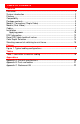
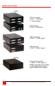
MODELS Models / Connectors (Single Video) PS/2 Transmitter (2-DVI-I / 1-MiniDin6 – “Y” cable needed) PS/2 Receiver (1-DVI-I / 2-MiniDin6) USB Transmitter (2-DVI-I / 1-USB type B) USB Receiver (1-DVI-I / 2-USB type A) Transmitter / Receiver (1-Power / 1-Fiber type LC) 4 CRYSTALVIEW DVI FIBER INSTALLATION AND OPERATIONS MANUAL
Models / Connectors (Single Video – Serial / Audio) PS/2 Transmitter (2-DVI-I / 1-MiniDin6 – “Y” cable needed) PS/2 Receiver (1-DVI-I / 2-MiniDin6) USB Transmitter (2-DVI-I / 1-USB type B) USB Receiver (1-DVI-I / 2-USB type A) Transmitter / Receiver (1-Power / 1-Fiber type LC) CRYSTALVIEW DVI FIBER INSTALLATION AND OPERATIONS MANUAL 5
Models (Dual Video) REAR PS/2 Transmitter (4-DVI-I / 1-MiniDin6) ”Y” cable needed PS/2 Receiver (2-DVI-I / 2-MiniDin6) USB Transmitter (4-DVI-I / 1-USB Type B) USB Receiver (2-DVI-I / 2-USB Type A) FRONT Transmitter (Front-All) (1-Power / 2-Fiber type LC) Bottom connector carries video 1 and keyboard/mouse data, top connector carries video 2.
Models (Dual Video – Serial / Audio) REAR PS/2 Transmitter (4-DVI-I / 1-MiniDin6) ”Y” cable needed PS/2 Receiver (2-DVI-I / 2-MiniDin6) USB Transmitter (4-DVI-I / 1-USB Type B) USB Receiver (2-DVI-I / 2-USB Type A) FRONT Transmitter (Front-All) (1-Power / 2-Fiber type LC) Bottom connector carries video 1 and keyboard/mouse data, top connector carries video 2.
Cables (See Attachment B for cable part numbers) Transmitter unit to CPU cable CPU cables connect from the transmitter to a CPUs keyboard, video monitor and mouse ports. A “Y” PS/2 cable for the keyboard and mouse are needed. Receiver to KVM station cable The keyboard, video monitor, and mouse cables on a KVM station can connect directly to the receiver or a transmitter with local KVM access.
INSTALLATION Installation Please refer to the safety section first before proceeding with any installation or configuration of the CrystalView DVI Fiber. When installing the CrystalView DVI Fiber, locate the transmitter as close as possible to the CPU or switch. Keep the cables as short as possible but still give some freedom of movement. You can mount the CrystalView DVI Fiber in a CPU rack with the optional rack mount kit.
To 2nd DVI Graphic card To 1st DVI Graphic card To 2nd DVI local monitor To 1st DVI local monitor To CPU USB or USB hub for keyboard and mouse Transmitter to Receiver cabling Cable type (w/ LC connectors) 62,5µm Multimode-Fiber 50.0µm Multimode-Fiber 9.0µm Singlemode-Fiber Maximum distance 650 ft / 200 m 1300ft / 400m 33,000ft / 10,000m Table 1.
Diagnostic LED Indicators VIDEO OK POWER DATA ERROR STATUS Power (Red) Off – No power applied, device not ready On- Power applied, device ready Data Error (Green) • Off - No errors, device ready • Blinking / On – Transmitter / Receiver communication not established Link Status (Green) • Blinking – No Fiber cable connection detected • On – Transmitter / Receiver communication established, device ready Video OK (Green) • Off – No video signal detected • On – Video signal detected, device ready CRYSTAL
OPERATION Operating instructions Operation of your computer is no different than having your keyboard, monitor, and mouse connected directly to the computer. All functions, applications, upgrades and other items can be done normally. The only difference is the computer can be up to 33,000 feet away. Local access on the CrystalView DVI Fiber allows an additional KVM station to be connected to the transmitter.
Carefully remove the four (4) Phillips screws from the bottom of the unit. If your model is a dual version, also remove the UNC screws that secure the video connectors. A- Remove the top cover exposing the internal PC board as shown below B- Locate jumpers JP1 and JP2.
5. Wait until the STATUS LINK LED illuminates 6. Connect the remote monitor’s video cable to the remote unit. (Turn on the remote monitor power if power is off) 7. The remote monitor’s DDC information will be read automatically, transferred to the local unit and stored into the DDC EPROM table. 8. The video OK LED on the local unit will blink rapidly for approximately 1 second upon successful programming of the remote DDC information. 9. Switch off the power on the local and remote units. 10.
Selecting moment of switching to next frame Normally the transmission of screen data is terminated when a frame is displayed on the screen. If the video source switches to a new frame during this display period, horizontal screen breaks may be seen. Jumper JP3 on the Remote unit’s PC board can be set to change the moment of switching. Remove the cover on the Remote unit and set JP3 accordingly.
TROUBLESHOOTING Troubleshooting The troubleshooting section is used as a guide to understanding the capabilities of the CrystalView DVI Fiber and for general troubleshooting. If you have any problems or questions concerning the installation, operation or usage of the CrystalView DVI Fiber that is not covered in this manual, please contact Rose Electronics for technical support. There isn’t a picture. • Check the power supply connection at the Local unit.
SERVIDE Service Information Maintenance and Repair This Unit does not contain any internal user-serviceable parts. In the event a Unit needs repair or maintenance, you must first obtain a Return Authorization (RA) number from Rose Electronics or an authorized repair center. This Return Authorization number must appear on the outside of the shipping container. See Limited Warranty for more information.
SAFETY Safety The CrystalView DVI Fiber KVM extender has been tested for conformance to safety regulations and requirements, and has been certified for international use. Like all electronic equipment, the CrystalView DVI Fiber should be used with care. To protect yourself from possible injury and to minimize the risk of damage to the Unit, read and follow these safety instructions. 18 Follow all instructions and warnings marked on this Unit.
Safety and EMC Regulatory Statements Safety information Documentation reference symbol. If the product is marked with this symbol, refer to the product documentation to get more information about the product. WARNING A WARNING in the manual denotes a hazard that can cause injury or death. CAUTION A CAUTION in the manual denotes a hazard that can damage equipment. Do not proceed beyond a WARNING or CAUTION notice until you have understood the hazardous conditions and have taken appropriate steps.
APPENDICES Appendix A. General specifications Maximum resolution 1920 x 1200 @ 60Hz over all allowed distances all lower resolutions with refresh rates of at least 75Hz Video compatibility DVI-D Keyboard PS/2 or USB Mouse PS/2 or USB Power adapter 90-240 VAC adapter to 5VDC / app.
Appendix B.
Appendix C. Rackmount Kit Rack mounting the CrystalView DVI Fiber uses the rackmount kit part number RM-BR3. You can mount 1 to 4 units on a single shelf and mount the shelf in a standard 19” rack. The units can be orientated on the rack with either the front or rear panel facing to the front or rear of the shelf. Mounting holes in the bottom of the shelf will lineup with the holes in the bottom of the unit. Provide adequate strain relief for all connected cables to avoid excess tension on the connectors.
10707 Stancliff Road Houston, Texas 77099 Phone: (281) 933-7673 WWW.ROSE.