PC SHARING SYSTEM INSTALLATION AND OPERATIONS MANUAL 10707 Stancliff Road Houston, Texas 77099 Phone: (281) 933-7673 WWW.ROSE.
LIMITED WARRANTY ® Rose Electronics warrants the MultiStation PC™ to be in good working order for one year from the date of purchase from Rose Electronics or an authorized dealer. Should this product fail to be in good working order at any time during this one-year warranty period, Rose Electronics will, at its option, repair or replace the Unit as set forth below. Repair parts and replacement units will be either reconditioned or new. All replaced parts become the property of Rose Electronics.
FCC/IC STATEMENTS, EU DECLARATION OF CONFORMITY FEDERAL COMMUNICATIONS COMMISSION AND INDUSTRY CANADA RADIO-FREQUENCY INTERFERENCE STATEMENTS This equipment generates, uses and can radiate radio frequency energy and if not installed and used properly, that is in strict accordance with the manufacturer’s instructions may cause interference to radio communication.
TABLE OF CONTENTS Contents Disclaimer .............................................................................................. 1 System introduction ............................................................................... 1 Features ............................................................................................ 2 Compatibility ..................................................................................... 3 Package contents ....................................................
INTRODUCTION Disclaimer While every precaution has been taken in the preparation of this manual, the manufacturer assumes no responsibility for errors or omissions. Neither does the manufacturer assume any liability for damages resulting from the use of the information contained herein. The manufacturer reserves the right to change the specifications, functions, or circuitry of the product without notice.
Features With the MultiStation PC you get all the benefits of a second computer without the expense of purchasing another computer. Allows multiple users to use one computer at the same time. Video resolution up to 1280 x 1024 x 16 bit High Color at 60 Hz 1024 x 768 x 32 bit True Color at 75Hz 800 x 600 x 32 bit True Color at 85Hz g g g Each user can work independently on the same or different application with no interference.
Compatibility Computers PC compatible running Microsoft Windows XP (SP1 & SP2) or 2000 (SP2) P III or higher computer, Athlon AMD, Intel Celeron, and Intel, 848P + Chipsets.
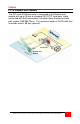
HARDWARE Hardware Front Remote user module Rear Remote user module PCI card Figure 1.
Cables PC to Remote user module The PCI cards RJ45 connector is connected to the Remote user module with up to 15 feet of standard CAT5 STP “solid core” cable terminated with RJ45 connectors (included). Rose Electronics cable part number CAB-08STPnnn. The maximum length of CAT5 cable that should be used is 50 feet (optional).
INSTALLATION Installation Please refer to the safety section first before proceeding with any installation or configuration of the MultiStation PC. Installation of the MultiStation PC is an addition to Microsoft Windows XP or Windows 2000 operating system and must be performed correctly. Due to the variations in computer systems, installation of the MultiStation PC on non-approved hardware may require assistance.
Installing the PCI card Ground yourself to a grounded metal object before installing the PCI card 1. Remove the computer cover and locate an un-used PCI slot on the motherboard 2. Install the MultiStation PC PCI card in the PCI slot by firmly applying uniform pressure on the top of the card until it seats properly in the PCI slot 3. Secure the PCI card with the proper size screw 4. Replace the computer cover Figure 2.
Installing the Remote user module (NOTE: Power to the computer should be off) Connect the remote keyboard, monitor, and mouse to the corresponding connectors on the remote user module. The local computer’s keyboard, monitor, mouse, and other cable connections such as a printer, scanner, or USB cables should already be connected to the corresponding ports on the computer. Remote User Station Figure 3.
Installing the software To install the MultiStation PC software, make sure all connections are secure and no applications are running. Login to Windows XP or 2000 with an account that has administrator privilege. Close any applications that might be running and insert the MultiStation PC CD. If the installation procedure does not start automatically, run the “Index.htm” program from the CD. From the "Index.
Figure 5. User information Next, enter the requested User information as shown in Figure 5. Enter the user information and serial number. (Note: serial # is located on the installation CD) When all information has been entered, click "Next". Figure 6. Destination folder You can install the MultiStation PC software in the default folder name “C:\Program Files\MultistationPC\” or change it to a folder name of your choosing by clicking on the “Browse” button.
Figure 7. Installation successful When the installation is complete, the final “Finish” screen will display. (Figure 7). Click on the “Finish” button and restart the computer to initialize and load the MultiStation PC software.
OPERATION User Operation When the shared computer is first booted, the boot-up sequence can be seen on the monitor connected to the computer. The monitor connected to the remote user module will remain blank until the computer fully boots up and the login screen displays. After the computer fully boots up, the monitor connected to the user module will change from a blank screen to a blue screen and then to its login screen.
OPERATION Figure 9. Station Properties Under “Local settings”, select “Stations” and double clicking on the station name to display the stations properties (Figure 9). The “Station” tab displays information about the selected station. Figure 10. Station options The ‘Option” tab (Figure 10) allows you to name the station, assign a Logon program, logon program folder, and automatically turn the station on when the system starts.
Figure 11. Start/Stop window The “Start/Stop” tab displays the station’s status and allows you to stop the station and shut down its windows desktop (Figure 11). Pressing the “Stop” button will stop the station. If the “Automatically turn station on when system starts” check box is not checked (refer to Figure 10), this button will display “Start” so you can start this station. Figure 12.
Figure 13. Broadcast message screen The “Broadcast” tab (Figure 13) is a feature that will broadcast a message to the other station. Type in your message in the message box and click “OK”. The text message will display on the other station in a pop-up message box (Figure 14). Figure 14.
SERVICE and SUPPORT Service Information Maintenance and Repair This Unit does not contain any internal user-serviceable parts. In the event a Unit needs repair or maintenance, you must first obtain a Return Authorization (RA) number from Rose Electronics or an authorized repair center. This Return Authorization number must appear on the outside of the shipping container. See Limited Warranty for more information.
SAFETY Safety The MultiStation PC has been tested for conformance to safety regulations and requirements, and has been certified for international use. Like all electronic equipment, the MultiStation PC should be used with care. To protect yourself from possible injury and to minimize the risk of damage to the Unit, read and follow these safety instructions. n n n n n n n n n n Follow all instructions and warnings marked on this Unit.
Safety and EMC Regulatory Statements Safety information Documentation reference symbol. If the product is marked with this symbol, refer to the product documentation to get more information about the product. WARNING A WARNING in the manual denotes a hazard that can cause injury or death. CAUTION A CAUTION in the manual denotes a hazard that can damage equipment. Do not proceed beyond a WARNING or CAUTION notice until you have understood the hazardous conditions and have taken appropriate steps.
TROUBLESHOOTING Keyboard or mouse on remote user module does not work. Cable is loose; re-seat keyboard or mouse cable at the CPU and the remote user module and reset the keyboard and mouse (Refer to Figure 12) n Keyboard and mouse cables reversed. n Boot-up sequence appears on the Remote user module monitor only n The system BIOS is detecting the MultiStation PC graphic adapter as the main display adapter.
2. Select “BIOS Features Setup”, enter “VGA Boot from”, and select the option “AGP” 3. Select “Integrated Peripherals” and press enter. Select “Init Display First”, then select “Enabled”. 4. Select “PNP, PCI & ON-BOARD I/O” and then select the “Init Display First” option.
APPENDICES Appendix A. General specifications MultiStation PC PCI card Bus Interface PCI bus V2.
Appendix B. Parts and cables Part Number KVM-PC42M CAB-08STP015 Description MultiStation PC PCI card /Module CAT5 cable Appendix C. Tested hardware list Motherboard Manufacturer D865GBF/D865PERC D865PERL P4R800-VM P4PE-X AB-BH6 845G MAX PT880Neo NS-7008 Ver1 PA2013 M7NBA3 M7NCG Pro Ver1.1 K7VTA3 V.
10707 Stancliff Road Houston, Texas 77099 Phone: (281) 933-7673 WWW.ROSE.