INSTALLATION AND OPERATIONS MANUAL 10707 Stancliff Road Houston, Texas 77099 Phone (281) 933-7673 WWW.ROSE.
LIMITED WARRANTY Rose Electronics warrants the MultiStation™ to be in good working order for one year from the date of purchase from Rose Electronics or an authorized dealer. Should this product fail to be in good working order at any time during this one-year warranty period, Rose Electronics will, at its option, repair or replace the Unit as set forth below. Repair parts and replacement units will be either reconditioned or new. All replaced parts become the property of Rose Electronics.
FCC/IC STATEMENTS, EU DECLARATION OF CONFORMITY FEDERAL COMMUNICATIONS COMMISSION AND INDUSTRY CANADA RADIO-FREQUENCY INTERFERENCE STATEMENTS This equipment generates, uses, and can radiate radio frequency energy and if not installed and used properly, that is, in strict accordance with the manufacturer’s instructions, may cause interference to radio communication.
TABLE of CONTENTS Content Page Disclaimer ......................................................................................................... 1 About this manual ............................................................................................. 1 Introduction ....................................................................................................... 1 Features ...........................................................................................................
Figures_ Page Figure 1. ML-2U Front Panel ............................................................................ 4 Figure 2. ML-2U Rear Panel ............................................................................. 5 Figure 3. ML-4U Front Panel ............................................................................ 6 Figure 4. ML-4U Rear Panel ............................................................................. 7 Figure 5, MLK-2U Front Panel .......................................
INTRODUCTION Disclaimer While every precaution has been taken in the preparation of this manual, the manufacturer assumes no responsibility for errors or omissions. Neither does the manufacturer assume any liability for damages resulting from the use of the information contained herein. The manufacturer reserves the right to change the specifications, functions, or circuitry of the product at any time without notice.
This manual describes all three models of MultiStation units. The features and commands are identical for the three models. Please disregard the diagrams and text that do not apply to your model. To acquaint you with your MultiStation unit, this manual first describes MultiStation’s front and rear panels. Installation and operation instructions show easy to understand diagrams that illustrates how to connect MultiStation to your computer, keyboards, video monitors, and mice.
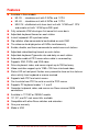
Features Available in three models: ML-2U - standalone unit with 2 KVMs and 1 CPU ML-4U - standalone unit with 4 KVMs and 1 CPU MLK-2U – distributed units have local unit with 1 KVM and 1 CPU and remote unit with 1 KVM up to 250’ apart Fully automatic KVM sharing on first-come first-serve basis Adjustable keyboard timeout on each station Instant keyboard LED synchronization Dip switches allow commands to be disabled on each KVM The video can be displayed on all KVMs simulta
PANEL DESCRIPTION Front panel – model ML-2U Dip Switch Remote Video LED Status LEDs Power LED KVM connectors Computer connector Figure 1. ML-2U Front Panel Table 1. Front panel - model ML-2U Dip Switch Configuration Power LED Status LEDs Remote Video LED Keyboardvideo-mouse (KVM) connectors Computer connector Enables commands from keyboard at each KVM station. Up is enable, down is disable.
Rear panel – model ML-2U RS232 Connector Power Switch Power Connector Figure 2. ML-2U Rear Panel Table 2. Rear panel - model ML-2U RS232 Power switch Power connector RS232 serial port for factory diagnostics only Pressing the switch turns the unit on, provided supplied power transformer is properly connected. Power transformer included in package connects here. This is not a keyboard input. Power transformers are available for U.S. or international use. Input voltage is 17VAC with center tap.
Front panel – model ML-4U Dip Switch Remote Video LED Status LEDs Power LED Keyboard-VideoMouse connectors Computer connector Figure 3. ML-4U Front Panel Table 3. Front panel - model ML-4U Dip Switch Configuration Power LED Status LEDs Remote Video LED Keyboardvideo-mouse (KVM) connectors Computer connector Enables commands from keyboard at each KVM station. Up is enable, down is disable.
Rear panel – model ML-4U RS 232 Connector Power Power switch connector Figure 4. ML-4U Rear Panel Table 4. Rear panel - model ML-4U RS232 Power switch Power connector RS232 serial port for factory diagnostics only Pressing the switch turns the unit on, provided supplied power transformer is properly connected. Power transformer included in package connects here. This is not a keyboard input. Power transformers are available for U.S. or international use. Input voltage is 17VAC with center tap.
Front panel – model MLK-2U LOCAL UNIT Dip Switch Remote Video LED Status LEDs Power LED Keyboard-VideoMouse connectors Computer connector REMOTE UNIT Status LEDs Power LED Keyboard-Video-Mouse connectors Figure 5, MLK-2U Front Panel Table 5. Front panels - model MLK-2U Dip Switch Configuration Power LED Status LEDs Remote Video LED Keyboardvideo-mouse (KVM) connectors Computer connector Only present on the local unit. Enables commands from keyboard at each KVM station. Up is enable, down is disable.
Rear panel – model MLK-2U LOCAL UNIT REMOTE UNIT Figure 6. MLK-2U Rear Panel Table 6.
INSTALLATION Installation procedure Step 1. Connecting the keyboards, monitors, and mice The Keyboard-Video-Mouse adapter cable connects one keyboard, one video monitor, and one mouse to the MultiStation. Cables will vary depending upon the connector type on your keyboard and whether you are using a PS/2 or serial mouse. You should have the correct cable to match your equipment’s connectors. These cables are available where you purchased your MultiStation. 1.
Step 2. Connecting the computer A CPU adapter cable connects your computer to the MultiStation. The cable type will vary depending on the computer’s keyboard and mouse connectors. 2.1 Connect the CPU adapter cable’s DB-25M connector to the DB-25F connector labeled CPU on the MultiStation front panel. 2.2 Connect the keyboard, mouse, and monitor connectors on the CPU adapter cable to the corresponding ports on the computer. MLK-2U Transmitter ML-4U ML-2U Figure 8.
Step 3. Connecting the bus cable (model MLK-2U only) Step #3 applies to MultiStation model MLK-2U only. If your model is model ML-2U or ML-4U, skip this step. The bus cable (13W3M / 13W3M) connects between the local MultiStation and the remote unit. 3.1 Connect one end of the bus cable to the local unit’s “BUS OUT” 13W3F connector. 3.2 Connect the other end of the bus cable to the remote unit’s “BUS IN” 13W3F connector. Figure 9.
Step 4. Powering up the system 4.1 Connect the provided power adapter(s) to the power connector on the rear panel of MultiStation and to a power strip or wall outlet. Model MLK-2U requires two power adapters, one for the local unit and one for the remote unit. 4.2 Turn on all KVM video monitors. 4.3 Push the ON/Off switch on the rear panel to turn on the unit.
OPERATION Dip Switch Settings The front panel dip switch enables or disables commands from each KVM station. To enable commands from a KVM station put the corresponding dip switch in the up position. To disable commands, put the switch in the down position. The dip switch on the right controls KVM #1, the next switch controls KVM #2, and so on. The below table shows the dip switch configuration and each settings function.
Keyboard Command Summary Table 8 is a summary of the available keyboard commands. See the detailed descriptions for an expanded explanation of each command. [Ctrl] in the Key Sequence column is a press and release of the right control key followed by the command.
Keyboard Command Detailed Descriptions NOTE: Follow all inputs that require entering a numeric value by the KEEP command to save the change. Reset Command (Right Ctrl + R) The reset command is used to reinitialize the mouse and keyboard without cycling power on the MultiStation. This command is rarely issued on newer operating systems. Older systems running DOS and Win 3.1 may need to issue this command or you are running an application that does not use a mouse or disables the mouse.
Mode command (Right Ctrl + M + 1, 2, or 3 + Enter) MultiStation automatically detects the computer’s keyboard mode upon computer boot-up. If the computer is already booted and then connected to MultiStation, the computer’s keyboard mode can not be detected and the mode stored in non-volatile memory is used. If the mode is incorrect, either re-boot the computer or issue the correct mode command.
RS232 mouse type (Right Ctrl + Q + value + Enter) This command is used to match your KVM station’s mouse to the mouse type used on the connected computer. The default command value is 0 for autodetect. If the KVM station’s mouse type is the same as the computer’s mouse this command does not need to be issued (PS/2 to PS/2 or Serial to Serial). If the KVM mouse is different than the computer’s mouse, then issue the command using the appropriate command value from table 10. Valid entries are 0, 1, or 2.
Power interruption MultiStation is immune to most power interruptions of less than three seconds. Since the keyboard power is supplied from MultiStation, you may need to reset it if a power interruption happens. Video distance capability The limitation on driving distance is usually due to the quality of the video. Table 11 shows the distances, resolution and quality of video that can be expected.
RACKMOUNTING Rackmount kit Rackmount kits are available to mount your MultiStation in a 19”, 23”, or a 24” rack. See appendix C for description and part numbers. The optional rack mount kit includes the following items: Black anodized rack mounting shelf Four mounting screws.
TROUBLESHOOTING TroubleShooting The troubleshooting section is used as a guide to understanding the capabilities of the MultiStation and for general troubleshooting. If you have any problems or questions concerning the installation, operation or usage of the MultiStation that is not covered in this manual, please contact Rose Electronics for technical support.
e. If you are using model MLK-2U and can not access the computer from the remote unit, check the power on the local unit or the bus cable is disconnected. Check the status LEDs on the local and remote unit. If they are not flashing at 1 second intervals, the bus cable may have a problem. 5. Can’t access all functions of mouse a. The Microsoft IntelliMouse or other similar wheel mice are not supported at this time. b. If Microsoft Ball Point mouse, get the latest mouse drivers. 6. Mouse does not move a.
SAFETY Safety The MultiStation has been tested for conformance to safety regulations and requirements, and has been certified for international use. Like all electronic equipment, the MultiStation should be used with care. To protect yourself from possible injury and to minimize the risk of damage to the Unit, read and follow these safety instructions. Follow all instructions and warnings marked on this Unit.
SERVICE and SUPPORT Maintenance and Repair This Unit does not contain any internal user-serviceable parts. In the event a Unit needs repair or maintenance, you must first obtain a Return Authorization (RA) number from Rose Electronics or an authorized repair center. This Return Authorization number must appear on the outside of the shipping container. See Limited Warranty for more information.
APPENDICES Appendix A. General Specifications Dimensions ML-2U/MLK-2U local/remote ML-4U 8.85”W x 2.10”H x 4.90”D 13.1”W x 5.25”H x 4.90”D Weight ML-2U/MLK-2U local/remote ML-4U 3.0 lbs 7.0 lbs Input Power 117 VAC adapter, 230 VAC optional Output Power 17VAC CT, 1.
Appendix C. Parts and Cables Part Number Description Keyboard / Monitor / Mouse Adapter Cables CAB-ZX0606Mxx VGA (HD15F) / PS/2 (MD6F) / PS/2 (MD6F) CAB-CX0606Mxx UltraCable VGA (HD15F) / PS/2 (MD6F) / PS/2 (MD6F) Computer Adapter Cables CAB-ZX0606Cxx VGA (HD15M) / PS/2 (MD6M) / PS/2 (MD6M) CAB-CX0606Cxx UltraCable VGA (HD15M) / PS/2 (MD6M) / PS/2 (MD6M) Bus Cable CAB-SMBxx Coax bus cable 13W3M to 13W3M xx = cable length in feet Note: Serial mouse and AT keyboard cables are available.
STANDALONE 2 KVMs to 1 CPU (Model ML-2U) STANDALONE 4 KVMs to 1 CPU (Model ML-4U) DISTRIBUTED 2 KVMs to 1 CPU (Model MLK-2U) MULTISTATION INSTALLATION AND OPERATIONS MANUAL 27
NOTES 28 MULTISTATION INSTALLATION AND OPERATIONS MANUAL
10707 Stancliff Road Houston, Texas 77099 Phone (281) 933-7673 WWW.ROSE.