UltraConsole Remote 2™ KVM MATRIX SWITCH WITH REMOTE ACCESS INSTALLATION AND OPERATIONS MANUAL 10707 Stancliff Road Houston, Texas 77099 Phone (281) 933-7673 www.rose.
LIMITED WARRANTY Rose Electronics warrants the UltraConsole™ Remote 2 to be in good working order for one year from the date of purchase from Rose Electronics or an authorized dealer. Should this product fail to be in good working order at any time during this one-year warranty period, Rose Electronics will, at its option, repair or replace the Unit as set forth below. Repair parts and replacement units will be either reconditioned or new. All replaced parts become the property of Rose Electronics.
TABLE of CONTENTS Contents Page # Disclaimer ........................................................................................................................................................................ 1 Introduction ...................................................................................................................................................................... 1 About this manual ..............................................................................................
Figure Page # Figure 1. Typical Single Unit Application ........................................................................................................................ 5 Figure 2. Configuration Menu.......................................................................................................................................... 7 Figure 3. Unit Configuration Menu ................................................................................................................................
INTRODUCTION Disclaimer While every precaution has been taken in the preparation of this manual, the manufacturer assumes no responsibility for errors or omissions. Neither does the manufacturer assume any liability for damages resulting from the use of the information contained herein. The manufacturer reserves the right to change the specifications, functions, or circuitry of the product at any time without notice.
Features Available in different models designed to meet your remote access needs Connect to remote devices locally, from any workstation on your network or over the internet using a web browser and the very secure VNC Viewer.
Cable requirements The cable requirements for your system will vary depending on the types of equipment connected to the UltraConsole Remote 2 and the equipment used for the local KVM station. A KVM cable is needed for the local KVM station, a CPU cable for each device connected to the UltraConsole Remote 2, expansion cables if the system is expanded in a BUS or RING configuration, and a cable to connect the unit your network.
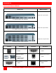
MODELS UltraConsole Remote 2 Models Rear Panel Model Number Single user / 4 port model 1 x 4 (Model number UCR-1R1X4U/2 Single user / 8 port model 1 x 8 (Model number UCR-1R1X8U/2) Single User / 16 port model 1 x 16 (Model number UCR-1R1X16U/2) Connector Description Power Connector IEC320 JP1 Expansion card(s) Connectors Connector Description KVM Connector DB25F RS232 Serial connector RJ12F DB15M (Output) DB15F (Input) CPU Connector DB25F 4 Network connector RJ45F ULTRACONSOLE REMOTE 2 INST
OVERVIEW System overview The UltraConsole Remote 2 is designed with the latest in KVM switching and remote access technology. It provides a comprehensive solution for local and remote server access. Local access is from a KVM station connected directly to the UltraConsole Remote 2. Remote access is from any Windows based workstation on your network. An unlimited number of workstations can be set-up to access the UltraConsole Remote 2, but a maximum of 4 remote users can be connected simultaneously.
INSTALLATION UltraConsole Remote 2 Installation (Single unit) Connecting the hardware UltraConsole Remote 2 Connecting the KVM station Connect a local KVM station to the UltraConsole Remote 2’s KVM connector using a KVM adapter cable that is compatible with the local KVM equipment and cable connectors. The local KVM mouse must be a PS/2 type mouse, the keyboard a PS/2 type keyboard and the monitor should be equal or better in resolution and capability than any connected computers.
UNIT CONFIGURATION Configuring the UltraConsole Remote 2 IP Input module When you locally connect to the UltraConsole Remote 2 unit for the first time the Unit must be configured to be compatible with your network. Follow the recommended procedure below to configure all models Make all cable connections to the KVM station and computers, connect to the network after the assigned unit IP address has been entered and saved.
Hardware and Firmware The versions for the unit are displayed in these fields. Data can not be changed. Keyboard Layout Using the left and right arrow keys, select the keyboard type expected from the host computers. Admin password Enter an administrator password of at least six characters that has a mix of letters and numerals. The background color provides an indication of password suitability. It is initially red to indicate that the password is not sufficient.
Screen #3 is a Secure Keys screen that will display after the network information has been entered. Figure 5. Secure Keys Encryption This screen uses mouse movements and keyboard inputs to create random data. This unpredictable information is then combined with several other factors to develop the basis of the encryption keys that are used to establish secure remote links. With every mouse move and key press the single dash will move across the progression bar (unless the same key is pressed repeatedly).
To view the menu options press . (If the standard hotkeys were altered on the Configure Unit screen, use the new hotkeys plus C) Logoff Select this option to close your current session and display the screensaver. Restore mouse functions Select this tab to revive a mouse that has ceased to function correctly. The UltraConsole Remote 2 provides a feature to reinstate PS/2 mouse communications. (Does not apply if using a USB mouse.
Connecting Remotely With the Unit and the Network configured properly, connect the unit to the network and start a web browser like IE or Netscape from any workstation connected to the network. Type in the UltraConsole Remote 2’s assigned IP address (Example (http://168.192.0.41) in the URL field. The UltraConsole Remote 2 will respond with the below screen.
User Accounts Allows you to create and manage up to fifteen separate user accounts, each with separate access permissions. Account #1 is the admin account. Enter User name, password. Tick/un-tick the Local and Remote options that are appropriate to the user. Unit Configuration Allows you to modify unit settings within the UltraConsole Remote 2.
User Name All user names must consist of lower case characters or numbers only. No symbols or upper case characters are permissible. The user name can be between 1 and 16 characters in length. Password Passwords are case sensitive and can include certain keyboard symbols. The password can be between 1 and 16 characters in length. The password background remains shaded in amber while the UltraConsole Remote 2 considers your entered password to be too easy to guess.
Screensaver Timeout Use the arrow keys to select an appropriate period of inactivity before a screensaver is displayed and the user is logged out. This setting applies to local users only and once the screensaver is displayed, for security purposes the user is required to log in again. The timeout period can be selected between 5 minutes and 1 day (24 hours), it cannot be disabled. Menu Bar Toggle Hot Key Use the arrow keys to select the hot key to use to toggle the menu bar on and off.
Protocol timeout Sets the time period by which responses should have been received to outgoing data packets. If the stated period is exceeded, then a connection is considered lost and terminated. Background refresh rate Use the arrow keys to alter the refresh rate for screen images via remote links. This allows you to tailor the screen refresh to suit the network connection speeds. The options are: Slow, Medium, Fast or Disabled.
Network Configuration This page allows you to configure the various aspects of the IP port and its relationship with the local network. MAC address Media Access Control address – this is the unique and unchangeable code that was hard coded within your UltraConsole Remote 2 unit when it was built. It consists of two 6-digit hexadecimal (base 16) numbers separated by colons.
IP Access Control This section allows you to optionally specify ranges of addresses which will or will not be granted access to the UltraConsole Remote 2. If this option is left unchanged, then the default entry of ‘+0.0.0.0/0.0.0.0’ ensures that access from all IP addresses will be permitted. If this feature is needed, please see Appendix F for a detailed explanation of IP access control.
Logging and Status This screen provides various details about the user activity on the UltraConsole Remote 2 . Note: The log has a maximum capacity of 1000 event lines. After 1000 entries, the oldest entries are overwritten. If log data are important to your installation, ensure a regular backup procedure or use the Syslog Server IP Address option to send log information automatically to another system. The first three (3) columns show the date the event occurred.
CONFIGURATION – SWITCH MODULE KVM Switch Module Menu structure To display the main switch module configuration menu connect to the UltraConsole Remote 2 locally or remotely and once connected and the host computers video displaying, press and release the left control key, then press the F12 key to display the switch modules configuration menu. Pressing the Alt + Ctrl + C key displays the IP input modules configuration menu.
Switch module - Main Menu (Pressing the left control key, then F12 displays the main menu) Figure 8. Main menu The Main configuration menu is the starting point for the configuration menus. From this menu, you can configure the system, computers, KVMs, users, profiles, groups, and languages. To display the “Main menu” press and release the left control [Ctrl] key, then the F12 key. The main menu will display on top of a currently connected computers video.
Configure System menu Figure 9. Configure system menu System settings selections. Configure password (Default: no password) The “Configure password” selection is used to add a new or change an existing administration password. This password prevents unauthorized access to the configuration menus. Passwords are case sensitive, 8 characters max. To create or change a password, select “Configure password” and press [Enter]. An input box will display to enter the password.
PC keyboard rate (chars/sec) (Default: 20) This option adjusts the KVM keyboard action when you hold down a key to repeat a single character. Valid inputs are 1-31. PC keyboard delay (Default: Fast) This option adjusts the delay between when a key is pressed and held and when it begins to send repeated characters to the selected computer.
Background / Text color (Default: Cyan / Black) This option sets the background or text colors for the connection status and computer select screens. Colors can be one of eight solid or transparent colors. To change the background or text color, select it from the menu and press [Enter]. The color selections will display showing the solid and transparent color choices. Use the arrow keys to select the desired color and press [Enter].
Computer name (Default: Computer x) To change the computer name, select it from the menu and press [Enter]. An input box will display to enter a new computer name. Type in the new name and press [Enter]. Names can be 16 characters in length, case sensitive. The computer name appears on the configure group menu, the computer select list and the connection status window. A diamond character next to a computer name identifies the computer currently connected to this KVM station.
Configure KVM menu Figure 11. Configure KVM menu The “Configure KVM” menu allows you to change the KVMs name, resolution, start, and user parameters. The ID column indicates the physical location (port) the KVM is connected to. The BUS column is the KVM video bus number. These values are not user changeable. KVM name (Default: KVM Station x) To change the KVM name, select it from the menu and press [Enter]. An input box will display to enter a new KVM name. Type in a new name and press [Enter].
The configure user, profile, and group menus all tie together to provide access control to the computers. A group defines which computers in the system can and cannot be accessed. This group is assigned to a profile name. The profile defines how the computers (defined by the group) can be accessed. The profile is assigned to a user or users. When a user logs on to the KVM Switch module, their assigned profile is validated.
Configure profile menu Figure 13. Configure Profile menu Name (Default: Profil x, where x = 1 to 80) The profile name can be changed to any name up to 8 characters in length. The name can be a specific user, a group of users within a department, a business department, or any name that defines the profile. To change the profile name, select the one to change and press [Enter]. An input box will display. Type in a new profile name and press [Enter].
Scan (Default: 5 seconds) When a user invokes the scan function, this feature sets the time the video is displayed before switching to the next sequential computers video. To change the scan rate, select the profile, then the scan rate to change and press [Enter]. An input box will display. Type in a new scan time and press [Enter]. Valid scan times are 0 to 9999.
Configure Language Figure 15. Configure language menu Selecting “Language” from the “Main” menu displays a choice box of different language options. Select the language needed and press [Enter]. This changes all the menu and display information to that selected language. The language options are: English Francais Deutsch Espanol Italiano* Portugues* * Italiano and Portugues languages are available on request.
System Status display Figure 16. System Status display The system status display is a very powerful and useful tool when installing, monitoring, expanding, troubleshooting, or reconfiguring a system. The status screen displays reported information from all CPU cards in the system. Computers Indicates the CPU port numbers for a given CPU card. Highlighted computer numbers are the total computer ports in the system. Power Each CPU card represents 4 CPU ports. These ports are represented by the four squares.
Save menu Figure 17. Save menu When changes are made to any configuration, they must be saved in flash memory to insure that the changes will be active after a power cycle. It is recommended that all users be logged off from all systems prior to saving any configuration changes. To save the settings, select save and press [Enter]. The UltraConsole will check and display how many CPU cards in the system to update.
INSTALLATION Switch Installation – Single Unit Please refer to the safety section before installation The basic installation of a single UltraConsole Remote 2 is an easy and straightforward procedure. Perform the below steps for all computers that will be connected. It is recommended that all computers be powered off. When a computer is connected and then booted, the UltraConsole Remote 2 will automatically determine the keyboard and mouse types used for that computer and no pre-configuration is needed.
Perform the following installation steps for each computer that will be connected to the UltraConsole Remote 2. Sequentially connect the computers starting with computer #1. STEPS: (Refer to the troubleshooting section for help if needed) 1. Connect a KVM station to the UltraConsole Remote 2s DB25F, KVM connector using the appropriate KVM cables. 2. Connect a computer to the UltraConsole Remote 2s DB25F, CPU #1 connector using the appropriate CPU cable. 3.
Switch Installation – Multiple units – “BUS” topology A “BUS” configuration is used when access to all computers is from the main unit #1. In a “BUS” configuration, (Figure 18) the video path is from the last Unit in the configuration to the first Unit (“OUT” to “IN”). A KVM user on the first Unit can access all computers on all Units. A user connected to Unit #2 can only access computers on Unit #2 and Unit #3, etc.
To start, identify the following prior to installation: 1. Which computers will be connected to the UltraConsole Remote 2 unit. 2. Which computers will be connected to the UltraConsole expansion units. 3. Which computers do not use a PC2 keyboard or a PS/2 mouse. 4. Which Unit and CPU port each computer will be connected to. 5. The “Starting computer” number for each Unit. 6. The number of computers, or “Maximum computers”, that the UltraConsole Remote 2 will be managing.
OPERATION Remote System Operation Connecting using a web browser / VNC Viewer Connecting to the UltraConsole Remote 2 from a network location or over the internet can be done two ways; using the Built-in Java VNC Viewer or Downloading Windows VNC Viewer from the unit and installing it on the remote computer. It is recommended that the Windows VNC viewer be downloaded from the unit and installed on the remote computer.
VNC Viewer Toolbar Figure 19 shows the VNC Viewer toolbar and an explanation of each toolbar tab. The VNC viewer uses a two mouse cursor technique to identify if you are working on the VNC Viewer or the remote PC’s desktop. The local cursor is the dot and the arrow cursor is the host computers desktop. When you move the cursor, the arrow cursor will follow the dot cursor.
Mouse Control This option displays a mouse control dialog box and is useful when the remote cursor is failing to respond correctly to your mouse movements, even after using the Re-sync and calibration mouse option. The mouse control dialog allows you to control the remote mouse cursor manually using a selection of buttons that you click with your local mouse. Additional options also allow you to restore the settings of a mouse that has failed to operate correctly.
Host Tab The “Host” tab on the toolbar allows you to easily switch to any CPU port on the unit or system. Each of the 128 Host locations can be set-up with the appropriate keyboard command to switch to that port. These keyboard commands are set-up from the “Configure, Host” tab. Using the Hosts tab method to switch between host computers assures that the screen calibration details for each host are reused.
Up to five users can be simultaneously logged-on (four remote users plus one local user) and during normal operation, all are able to see the same view of the currently selected host. If you need to perform a sensitive task that should not be viewed by other users, you can change the access mode to Private. This action blanks the viewer window for all other logged on users. Use the left or right arrow keys to switch between the Shared and Private mode.
SERIAL DEVICE SUPPORT Serial Device Support The serial feature allows you to connect a KVM station to a serial device such as the serial port on a UNIX or Sun computer, a communication device, or any device with a serial port. The serial device is connected to the DB25F CPU port on the UltraConsole Remote 2 with a serial cable (See Appendix C for serial cable part numbers). Any CPU port can be configured to be a serial port.
The page up and page down keys allow you to scroll the incoming pages in the four page scroll buffer. The F12 key clears the screen.
RS232 Port Serial port usage (RS232) The following procedure for establishing a connection from your standalone computer or Notebook computer to the UltraConsole Remote 2 switch’s serial port uses Windows HyperTerminal™. Refer to your user’s manual if a different communication program is being used. To access an UltraConsole Remote 2 serial port, the following items are required: A serial cable (RJ12, 6-wire connector and an appropriate adapter for the computer’s serial port).
Serial options menu 1) 2) 3) 4) 5) 6) 7) 8) Change starting computer number … 1 Change the serial port baud rate … 9600 Receive new main program or kernel from serial port (this card only) Send this unit’s main program to other units Send this unit’s kernel to other units Reset configuration data to factory defaults (this card only) Save changes made in 1 and 2 (this card only) Exit (restart the unit) Enter choice - - > Serial menu options Option 3, 4 and 5 are not available when using a display terminal
Option 3. Receive new main program or kernel from serial port (This card only) When new main or kernel programs are available, they can be obtained from Rose Electronics or downloaded from our web site at www.rose.com. The diagnostic screen that is displayed when the UltraConsole Remote 2 switch is first turned on shows the Kernel and main program version that is presently installed.
Option 4. Send this Unit’s Main Program to other Units. Option 5. Send this Unit’s Kernel to other Units. The main program or kernel program updates (Option 3) only have to be done on one port. Make sure power to all UltraConsole Remote 2 switches is “ON” and they are all connected using the appropriate expansion cables. Press 4 to send the main program to all other units, all other cards. Press 5 to send the kernel program to all other cards.
SERVICE and MAINTENANCE Service Information Maintenance and Repair This Unit does not contain any internal user-serviceable parts. In the event a Unit needs repair or maintenance, you must first obtain a Return Authorization (RA) number from Rose Electronics or an authorized repair center. This Return Authorization number must appear on the outside of the shipping container. See Limited Warranty for more information.
SAFETY Safety This UltraConsole switch has been tested for conformance to safety regulations and requirements, and has been certified for international use. Like all electronic equipment, the UltraConsole switch should be used with care. To protect yourself from possible injury and to minimize the risk of damage to this Unit, read and follow these safety instructions. Follow all instructions and warnings marked on this Unit.
Safety and EMC Regulatory Statements Safety Information Documentation reference symbol. If the product is marked with this symbol, refer to the product documentation to get more information about the product. WARNING A WARNING in the manual denotes a hazard that can cause injury or death. CAUTION A CAUTION in the manual denotes a hazard that can damage equipment. Do not proceed beyond a WARNING or CAUTION notice until you have understood the hazardous conditions and have taken appropriate steps.
TROUBLESHOOTING Troubleshooting Remote network users are unable to contact the unit Check that the correct address is being used by the remote users. Check the network settings. Check that the user’ network address has not been excluded in the IP access control section. If the UltraConsole Remote 2 is situated behind a firewall, check that the relevant ports are being allowed through the firewall and are being correctly routed. Check the front panel indicators, the LNK indicator should be on.
Mouse does not move The UltraConsole turned off after or not attached when computer booted or application began using mouse. Exit and re-enter application using mouse or issue reset command. PS/2 mouse was not attached when the UltraConsole powered up or has been detached and reattached. Issue the reset command. PS/2 mouse gets out of sync Reset the mouse by pressing and releasing the left Control Key, and then the R key. Cabling was disturbed during mouse movement.
APPENDICES Appendix A – Specifications Dimensions Weight Power Connectors Video Resolution Chassis Controls Environmental Width 16.7 Height 2 user/4 user 1.75 / 3.50 Depth 12.0 Units Inches 42.4 4.45 / 8.89 30.5 Centimeters 1 x 4 = 8 lbs. (3.
Appendix C – Rack mounting The rack mount kit includes the following items: Two black anodized mounting brackets Four 6 - 32 x 3/8” flat head mounting screws To rack mount your UltraConsole Remote 2, attach the two rack mounting brackets to your Unit with the short flange against the Unit using the four screws provided. Secure the mounting brackets to the rack using the appropriate size bolts, nuts and lock washers.
Appendix D – VNC Viewer Options When you are connecting to the UltraConsole Remote 2 using the VNC viewer, a number of options are available. Normally, the default settings for all the options are acceptable and provide for a safe, secure connection to the unit. If the color / Encoding / Scaling / Inputs / Identities / Load – Save options / or Misc. items need modifying, start the VNC viewer and click on the Options tab. This will invoke the VNC Viewer Options.
Scaling tab No Scaling No attempt is made to make the screen image fit the viewer window. You may need to scroll horizontally and/or vertically to view all parts of the screen image. Scale to Window Size Adjusts the server screen image to suit the size of the viewer window. Custom Size Adjusts the server screen image according to the Width and Height settings in the adjacent fields. A drop box to the right of the fields allows you to define the image size by percentage or by pixels, as required.
Disable all inputs (view-only mode) When selected, prevents control data being passed between server and viewer. Viewer can display the server output, but cannot control it. Customize Allows you to select which data can be transferred between server and viewer. Send pointer events to server - When un-ticked, the VNC viewer will not send mouse movement or click data to the UltraConsole Remote 2 or host system.
Full-screen mode uses all monitors This option does not apply to UltraConsole Remote 2 connections. Render cursor locally This option does not currently apply to UltraConsole Remote 2 connections. Allow dynamic desktop resizing When ticked, the viewer window will be automatically resized whenever the host system’s screen resolution is altered. Only use protocol version 3.3 This option does not apply to UltraConsole Remote 2 connections.
Load / Save Configuration File – Reload Allows you to load a configuration file saved from this, or another viewer. Configuration File – Save Allows you to save the current settings so that they can be copied from one viewer to another. Configuration File - Save As. Allows you to save the current settings under a new name so that they can be copied from one viewer to another. Defaults – Reload When clicked, all connection options are returned to the default settings that are currently saved.
Appendix E – Video Modes The following video modes are supported and can be automatically configured by the UltraConsole Remote 2. If a recognised video mode cannot be found, the UltraConsole Remote 2 will gradually change some of the key parameters to discover whether a video lock can be achieved. Support for VESA GTF (Generalized Timing Formula) is available and can be enabled via the Advanced Unit Configuration screen. The half width video modes capture every other pixel.
Appendix G – Allowable HOTKEY Sequences These codes are used when defining hotkey switching sequences (macros) for host computers and allow you to include almost any of the special keys on the keyboard.
10707 Stancliff Road Houston, Texas 77099 Phone (281) 933-7673 www.rose.