ULTRAVIEW REMOTE 2 KVM Access Over IP INSTALLATION AND OPERATIONS MANUAL 10707 Stancliff Road Houston, Texas 77099 Phone (281) 933-7673 Internet: WWW.ROSE.
LIMITED WARRANTY Rose Electronics warrants the UltraView Remote 2™ to be in good working order for one year from the date of purchase from Rose Electronics or an authorized dealer. Should this product fail to be in good working order at any time during this one-year warranty period, Rose Electronics will, at its option, repair or replace the Unit as set forth below. Repair parts and replacement units will be either reconditioned or new. All replaced parts become the property of Rose Electronics.
TABLE of CONTENTS Contents Page Disclaimer ........................................................................................................................................................................ 1 Introduction ...................................................................................................................................................................... 1 Features .........................................................................................................
Figures Page Figure 1. UltraView Remote 2 Models ............................................................................................................................ 5 Figure 2. Connecting a KVM ........................................................................................................................................... 6 Figure 3. Connecting Computers ....................................................................................................................................
INTRODUCTION Disclaimer While every precaution has been taken in the preparation of this manual, the manufacturer assumes no responsibility for errors or omissions. Neither does the manufacturer assume any liability for damages resulting from the use of the information contained herein. The manufacturer reserves the right to change the specifications, functions, or circuitry of the product without notice.
Features Six models available: 4-port model (PC or Multi-platform) 8-port model (PC or multi-platform) 16-port model (PC or multi-platform) Supports PC or Multi-platform systems Solid-state embedded unit, has no disk drive for maximum reliability Remote application (Real VNC or Java applet) can be installed directly from the unit Local KVM port for configuring and direct access to the connected computers Connect to the unit directly, from a network workstation, or over IP using any supported web browser.
Rose Electronics web site Visit our web site at www.rose.com for additional information on the UltraView Remote 2 and other products offered by Rose Electronics that are designed for data center applications, classroom environments, and many other access and switching applications. Product Registration Take advantage of the following when you register your Rose Electronics products online at http://www.rose.com/htm/online-registrationform.htm: Rose Standard Warranty Plus...
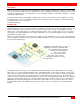
OVERVIEW System overview The UltraView Remote 2 is a versatile and powerful product that can extend the range of access to your computers from anywhere in the world. It is designed to provide seamless and trouble-free access from any workstation on your network or any remote user to any connected computer. You can connect to and control any of the connected computers by simple keyboard commands or an on-screen list of computers. Each computer can be assigned a unique name that makes sense for your system.
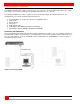
MODELS Connector Type Power IEC320 CPU (4) DB25F KVM (1) DB25F RS232 RJ12F Network RJ45F Connector Type Power IEC320 CPU (8) DB25F KVM (1) DB25F RS232 RJ12F Network RJ45F Connector Type Power IEC320 CPU (16) DB25F KVM (1) DB25F RS232 RJ12F Network RJ45F UPR-1R04UB/2 - UER-1R04UB/2 UPR-1R08UB/2 - UER-1R08UB/2 UPR-1R16UB/2 - UER-1R16UB/2 Figure 1.
INSTALLATION UltraView Remote 2 Installation Installing the UltraView Remote 2 is a very easy process and should be performed by a designated administrator. The administrator will install, configure, and set-up user access profiles. A network administrator will need to assign an IP address to the unit (if needed) and set-up firewall and network access to the unit. The following installation procedure is a guide to properly install and configure the UltraView Remote 2.
Connecting the Computers / Servers Connect each computer to the UltraView Remote 2 using the appropriate CPU adapter cable designed to interface to the type of computer being connected (PS/2, Unix, SUN, DEC, Apple, etc). Connect the DB25M end of the CPU adapter cable to the desired DB25F CPU port on the rear panel of the unit. Connect the other end of the cable to the corresponding ports on the computer (keyboard, monitor, and mouse). Refer to Figure 3.
Cascading units If your system demands are greater than a single model can provide, you can cascade the UltraView Remote 2 to other UltraView Pro or ServeView Pro models. The total number of cascaded units that can be added is equal to the total number of CPU ports on the unit identified as the “Master” unit.
UNIT CONFIGURATION Configuring the UltraView Remote 2 IP Input module When you locally connect to the UltraView Remote 2 unit for the first time the Unit and Network must be configured. Follow the recommended procedure below to configure all models: a. Make all cable connections to the KVM station, network, and computers b. Make sure power is applied to all devices (Computer, UltraView Remote 2, and Monitor). c. Make sure a computer is connected to CPU port #1 and that computer is powered on.
Keyboard Layout Using the left and right arrow keys, select the keyboard type expected from the host computers. Admin password Enter an administrator password of at least six characters that has a mix of letters and numerals. The background color provides an indication of password suitability. It is initially red to indicate that the password is not sufficient. When a password with reasonable strength has been entered it changes to blue. Time and Date Set the time and date to the correct values.
. Screen #3 is a secure keys screen that will display after the network information has been entered. Figure 9. Secure Keys Encryption This screen uses mouse movements and keyboard inputs to create random data. This unpredictable information is then combined with several other factors to develop the basis of the encryption keys that are used to establish secure remote links. With every mouse move and key press the single dash will move across the progression bar (unless the same key is pressed repeatedly).
To view the menu options press . (if the standard hotkeys were altered on the Configure Unit screen, use the new hotkeys plus C) Logoff Select this option to close your current session and display the screensaver. Restore mouse functions Select this tab to revive a mouse that has ceased to function correctly. The UltraView Remote 2 provides a feature to reinstate PS/2 mouse communications. (Does not apply if using a USB mouse.
Connecting Remotely With the Unit and the Network configured properly, start a web browser like IE or Netscape from any workstation connected to the same network your UltraView Remote 2 is connected to. Type in the UltraView Remote 2’s assigned IP address (Example (http://168.192.0.41) in the URL field. The UltraView Remote 2 will respond with the below screen. There may be initial login and connect screens displayed.
(Following describes each of the Configuration Tabs. Allows you to create and manage up to sixteen separate user accounts, each with User Accounts separate access permissions. Account #1 is the admin account. Enter User name, password. Tick/un-tick the Local and Remote options that are appropriate to the user. Unit Configuration Time & Date Configuration Allows you to modify unit settings within the UltraView Remote 2.
User Name All user names must consist of lower case characters or numbers only. No symbols or upper case characters are permissible. The user name can be between 1 and 16 characters in length. Password Passwords are case sensitive and can include certain keyboard symbols. The password can be between 1 and 16 characters in length. The password background remains shaded in amber while the UltraView Remote 2 considers your entered password to be too easy to guess.
Screensaver Timeout Use the arrow keys to select an appropriate period of inactivity before a screensaver is displayed and the user is logged out. This setting applies to local users only and once the screensaver is displayed, for security purposes the user is required to log in again. The timeout period can be selected between 5 minutes and 1 day (24 hours), it cannot be disabled. Menu Bar Toggle Hot Key Use the left or right arrow keys to choose the hot key to turn on or off the menu bar.
Background refresh rate Use the arrow keys to alter the refresh rate for screen images via remote links. This allows you to tailor the screen refresh to suit the network connection speeds. The options are: Slow, Medium, Fast or Disabled. When the disabled option is selected, the remote users will need to manually refresh the screen. Note: When a low connection speed is detected, the background refresh is automatically disabled, regardless of the settings of this option.
Network configuration This page allows you to configure the various aspects of the IP port and its relationship with the local network. MAC address Media Access Control address – this is the unique and unchangeable code that was hard coded within your UltraView Remote 2 unit when it was built. It consists of two 6-digit hexadecimal (base 16) numbers separated by colons.
HTTP Port This is the logical link that communications with a remote web browser will be channeled. The default setting of 80 is an established standard for web (HTTP – HyperText Transfer Protocol) traffic though this can be changed to suit your local network requirements. IP Access Control This section allows you to optionally specify ranges of addresses which will or will not be granted access to the UltraView Remote 2. If this option is left unchanged, then the default entry of ‘+0.0.0.0/0.0.0.
Hotkey / KVM Port Declare the hot key sequence, or Remote Port Direct address that will cause the KVM switch module to link with the required host system. Remote Port Direct addresses must be entered within square brackets.
KVM Switch Module Configuration Connect to the unit directly from the local KVM station. A computer must be connected to CPU port #1 and powered on. Using the local keyboard, press and release the Ctrl key, then within 2 seconds press the F12 key. The press and release of the Ctrl key notifies the KVM Switch module that the next command issued within 2 seconds is a command for the KVM Switch, not a connected computer. The F12 key will invoke the KVM switch modules OSD main menu shown below. Figure 12.
Configure System Figure 13. Configure system menu To configure the local keyboard or mouse type, use the up/down arrow keys and select keyboard or mouse and press enter. A display box will appear listing the choices for the keyboard or mouse. Use the up/down arrow keys to select the correct keyboard or mouse and press enter.
Scan settings The scan settings section determines the amount of time in seconds that a computer’s video is displayed before automatically switching to the next sequential computer. The scan mode can be turned on or off and set to automatically scan the computers when the UltraView is powered up. Scan time (seconds) To change the scan time, highlight “Scan time” and press enter. An input box will display for a new value. Enter the new scan time in seconds and press enter. Valid entries are 1 to 999.
Sun Language If the Sun keyboard type you are using is not a US Sun keyboard, the language can be changed to the correct language keyboard. To change the language type, select “Sun Language” and press enter. A list box will display showing the language choices available. Use the up/down arrow keys to select the correct Sun Keyboard language and press enter.
Keyboard choices PC1 PC2 PC3 USB-PC USB-Sun Apple* Sun* Mouse choices PS/2 PS/2 wheel Serial 2-button Serial 3-button * Available on multi-platform models only. Configure overlay The “Configure overlay” menu is used to configure the color of the menus, the resolution of the video when no computer video is present, the screen saver type and time, the computer select window appearance, and the displayed computer label.
Resolution Use this configuration to set the resolution for the KVM stations video if no computer video is present. To change the setting, select “Resolution” and press enter. A selection box will appear listing the choices. The default setting is PC2, 640 x 480 @ 60Hz.
Background color To change the background color, select “Background color” and press enter. A color selection box will display showing the available background colors. Use the arrow keys to select either a solid or transparent color and press enter. The default background color is Transparent blue.
Fade out (seconds) This controls how long the computer label displays before disappearing. A value of zero (0) disables this function and the label will not be displayed. A value of 255 causes the computer label to always be displayed. To change this value, select it and press enter. An input box will display for a new value. Enter the value wanted between 0 and 255 and press enter. ( D, will display the label at any time) Font This item sets the font type for the computer label.
Security The Security set-up provides an additional administrator and user access control system that is independent from the UltraView Remote 2 IP Access Module’s security system. The “Configure security” menu allows for setting a configuration password and an access password that apply to both a local user and a remote network user. The configuration password restricts access to the KVM switch module configuration menus and the access password limits access to the connected computers. Figure 16.
OPERATION Remote System Operation Connecting using a web browser Connecting to the UltraView Remote 2 from a network location or over the internet can be done two ways; using the Built-in Java VNC Viewer or Downloading Windows VNC Viewer from the unit and installing it on the remote computer. It is recommended that the Windows VNC viewer be downloaded from the unit and installed on the remote computer.
VNC Viewer Toolbar Figure 17 shows the VNC Viewer toolbar and an explanation of each toolbar tab. The VNC viewer uses a two mouse cursor technique to identify if you are working on the VNC Viewer or the remote PC’s desktop. The local cursor is the dot and the arrow cursor is the host computers desktop. When you move the cursor, the arrow cursor will follow the dot cursor.
Mouse Control This option displays a mouse control dialog box and is useful when the remote cursor is failing to respond correctly to your mouse movements, even after using the Re-sync and calibration mouse option. The mouse control dialog allows you to control the remote mouse cursor manually using a selection of buttons that you click with your local mouse. Additional options also allow you to restore the settings of a mouse that has failed to operate correctly.
Host Tab The “Host” tab on the toolbar allows you to easily switch to any CPU port on the unit or system. Each of the 128 Host locations can be set-up with the appropriate keyboard command to switch to that port. These keyboard commands are set-up from the “Configure, Host” tab. Using the Hosts tab method to switch between host computers assures that the screen calibration details for each host are reused.
Using the VNC Viewer and not the Java applet, you can also directly access the KVM switch module using keyboard commands or the Hosts feature. Using the Java applet, each keyboard commands to instruct the KVM Switch module to exercise an option must be configured to either the “Command, Keyboard Control” tab or the Hosts tab. The easiest way to switch to a CPU port is invoke the Computer select window. To do this using the VNC viewer, press and release the Ctrl key, then within 2 seconds, press the Esc key.
Keyboard Commands Keyboard commands can be used to further customize the KVM switch module. These commands can be invoked directly from a local or remote keyboard or from the “Command, Keyboard commands” tab on the VNC view toolbar.
Trouble Shooting Troubleshooting Remote network users are unable to contact the unit Check that the correct address is being used by the remote users. Check the network settings. Check that the user’ network address has not been excluded in the IP access control section. If the UltraView Remote-2 is situated behind a firewall, check that the relevant ports are being allowed through the firewall and are being correctly routed. Check the front panel indicators, the LNK indicator should be on.
Can’t switch computers from keyboard Power to the UltraView Pro was removed for less than three seconds possibly causing keyboard to lock up. Disconnect and re-connect the keyboard. If PS/2 type keyboard and mouse cables may be reversed. Not using left control key. Using numeric keypad instead of keys on top row. Not releasing control key before typing in number. Waiting more than 2 seconds to enter computer number. Using caps lock or shift key.
Service and Support Maintenance and Repair This Unit does not contain any internal user-serviceable parts. In the event a Unit needs repair or maintenance, you must first obtain a Return Authorization (RA) number from Rose Electronics or an authorized repair center. This Return Authorization number must appear on the outside of the shipping container. See Limited Warranty for more information.
SAFETY Safety This Unit has been tested for conformance to safety regulations and requirements, and has been certified for international use. Like all electronic equipment, the Unit should be used with care. To protect yourself from possible injury and to minimize the risk of damage to this Unit, read and follow these safety instructions. Caution! Risk of explosion can occur if the battery is replaced with an incorrect type. Dispose of used batteries according to the manufacturer’s instructions.
APPENDICES Appendix A – Specifications Dimensions Width Depth Height 4 / 8 port 16.7” / 42.4cm 15.2” / 38.6cm 1.75” / 4.5cm 16 port 16.7” / 42.4cm 15.2” / 38.6cm 3.50” / 9.0 cm Weight 4-port units 8-port units 16-port units 6.9 lbs / 3.1 kg 9.3 lbs / 4.2 kg 14.0 lbs / 6.
Appendix C - RackMount The rack mount kit includes the following items: Two black anodized mounting brackets Four 6 - 32 x 3/8” flat head mounting screws To rack mount your UltraView Remote 2 unit, attach the two rack mounting brackets to your Unit with the short flange against the Unit using the four screws provided. Secure the mounting brackets to the rack using the appropriate size bolts, nuts and lock washers.
Appendix E – IP Access Control Setting IP access control The golden rule with this feature is ‘Include before you exclude’ or to put it another way ‘Arrange allowed addresses in the list before the denied addresses’. This is because the positions of entries in the list are vitally important. Once a range of addresses is denied access, it is not possible to make exceptions for particular addresses within that range.
Ignoring the initial three octets, the final six zeroes of the mask would ensure that the 32 addresses from .64 (01000000) to .95 (01011111) would all be treated in the same manner. See Net masks - the binary explanation for details. When defining a mask, the important rule to remember is: There must be no ‘ones’ to the right of a ‘zero’.
Appendix F – VNC Viewer connection options When you are connecting to the UltraView Remote 2 unit using the VNC viewer, a number of options are available. Click the Options… button There are six tabbed pages of options: Color/Encoding Auto select When ticked, this option will examine the speed of your connection to the UltraView Remote 2 unit and apply the most suitable encoding method. This option is suggested for the majority of installations.
Scaling No Scaling No attempt is made to make the screen image fit the viewer window. You may need to scroll horizontally and/or vertically to view all parts of the screen image. Scale to Window Size Adjusts the server screen image to suit the size of the viewer window. Custom Size Adjusts the server screen image according to the Width and Height settings in the adjacent fields. A drop box to the right of the fields allows you to define the image size by percentage or by pixels, as required.
Misc Shared connection (do not disconnect other viewers) This option does not apply to UltraView Remote 2 unit. Full screen mode When ticked, the VNC viewer will launch in full screen mode. Use the menu key (usually F8) to exit from full screen mode. Full-screen mode matches server resolution This option does not apply to UltraView Remote 2 unit.
Load / Save Configuration File - Reload Allows you to load a configuration file saved from this, or another viewer. Configuration File - Save Allows you to save the current settings so that they can be copied from one viewer to another. Configuration File - Save As... Allows you to save the current settings under a new name so that they can be copied from one viewer to another. Defaults - Reload When clicked, all connection options are returned to the default settings that are currently saved.
Appendix H – Browser viewer options When you are connecting to the UltraView Remote 2 unit using a Web browser and the VNC applet, a number of options are available. Click the Options… button There are four options pages: Encoding and color level Auto select When ticked, this option will examine the speed of your connection to the UltraView Remote 2 and apply the most suitable encoding method. This option is suggested for the majority of installations.
Misc Shared (don’t disconnect other viewers) This feature is restricted to software server versions of VNC and has no effect on UltraView Remote 2 unit installations. Render cursor locally This feature is restricted to software server versions of VNC and has no effect on UltraView Remote 2 unit installations. Fast CopyRect This feature is restricted to software server versions of VNC and has no effect on UltraView Remote 2 unit installations.
Appendix J – Hotkey sequence codes These codes are used when defining hotkey switching sequences (macros) for host computers and allow you to include almost any of the special keys on the keyboard.
Appendix K – Video distance capability The table below shows the distances, resolution, and quality of video that can be expected with normal or coax cabling. This table applies to the MASTER unit only. There will be some degradation when units are chained together.
NOTES:
10707 Stancliff Road Houston, Texas 77099 Phone: (281) 933-7673 WWW.ROSE.