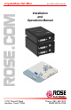
CrystalView DVI Mini DVI, USB 2.0 CATx Extender Installation and Operations Manual 10707 Stancliff Road Houston, Texas 77099 Phone: (281) 933-7673 WWW.ROSE.
LIMITED WARRANTY Rose Electronics warrants the CrystalView DVI Mini to be in good working order for one year from the date of purchase from Rose Electronics or an authorized dealer. Should this product fail to be in good working order at any time during this one-year warranty period, Rose Electronics will, at its option, repair or replace the Unit as set forth below. Repair parts and replacement units will be either reconditioned or new. All replaced parts become the property of Rose Electronics.
CE Declaration Of Conformity The products listed below in the form as delivered comply with the provisions of the following European Directives: 2004/108/EG Council Directive on the approximation of the laws of the Member States relating to electromagnetic compatibility CE Marking 2009 Product list: CRK-M1DTXUD1D / CRK-M1DTXUD2D CRK-M1DTXTD1D / CRK-M1DTXTD2D The products comply with the following harmonized standards for Information Technology Equipment: • EN 55022:2006 + A1:2007 (Class A) • EN 55024:1998
TABLE of CONTENTS CONTENTS PAGE # System Introduction ............................................................................................. 2 Disclaimer ............................................................................................................ 2 About This Manual .............................................................................................. 3 Product Registration ............................................................................................
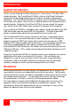
INTRODUCTION System Introduction Thank you for choosing the Rose Electronics CrystalView DVI Mini KVM station extender. The CrystalView DVI Mini is the result of Rose Electronics commitment to providing state-of-the-art solutions for today’s demanding workplace. The CrystalView DVI Mini has proven to be a valuable investment for any business, big or small, that has a need to access their computer from a remote location. Using the CrystalView DVI Mini, you can locate the remote user station up to 165ft.
INTRODUCTION About This Manual This manual covers the installation, configuration, and the operation of the CrystalView DVI Mini extender system. The system consists of a transmitter and receiver units, a computer to remotely access, and a remote KVM user station for remote access to the computer. The “Model” section describes the front and rear panel of the transmitter and receiver units. The “Installation” section describes how all components are interconnected and configured.
Features Single-Link - single or dual head models available Single head supports: 1 DVI-D graphic card and 2 USB HID devices or 1 DVI-D graphic card and USB 2.0 devices Dual head supports: 2 DVI-D graphic cards and 2 USB HID devices or 2 DVI-D graphic cards, 2 HID devices, and USB 2.
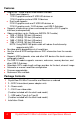
MODELS CrystalView DVI Mini Models The CrystalView DVI Mini is available in the following models: Single head USB HID – part number CRK-M1DTXUD1D Transmitter - Front View DVI-D video input USB Type B Transmitter - Rear View Power +5VDC Programming port Configuration Dip switches RJ45 Receiver – Front View DVI-I video output 2 – USB HID Type A Receiver – Rear View Power +5VDC Programming port Configuration Dip switches RJ45 Figure 1.
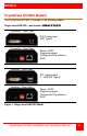
Dual head USB HID – part number CRK-M1DTXUD2D Transmitter - Front View 2-DVI-D video input 2-USB Type B Transmitter - Rear View Power +5VDC Option 2-Programming ports 2- Configuration Dip switches 2-RJ45 connectors Receiver – Front View 2-DVI-I video outputs 4-USB HID Type A Receiver – Rear View Power +5VDC 2-Programming ports 2-Configuration Dip switches 2-RJ45 Link Figure 2. Dual head USB HID Model NOTE: Single and Dual head USB-HID models support two and only two USB-HID devices.
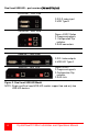
Single head USB 2.0 – part number CRK-M1DTXTD1D Transmitter - Front View DVI-D video input USB 2.0 Type B Transmitter - Rear View Power +5VDC Programming port 2-RJ45 Link Configuration Dip switches Receiver – Front View DVI-I video output 4 – USB 2.0 Type A Receiver – Rear View Power +5VDC Programming port 2-RJ45 Link Configuration Dip switches Figure 3. Single head USB 2.
Dual Head USB 2.0 - CRK-M1DTXTD2D Transmitter - Front View 2-DVI-D video input 2-USB Type B Transmitter - Rear View Power +5VDC Option 2-Programming ports 3-RJ45 Link ports 2-Configuration Dip switches Receiver – Front View 2-DVI-I video outputs 2-USB HID Type A 4-USB 2.0 Type A Receiver – Rear View Power +5VDC 2-Programming ports 2-Configuration Dip switches 3-RJ45 Link Figure 4. Dual head USB 2.
Compatibility Video Supports all DVI-D video signals that comply to the DVI-D Single Link protocol. This includes resolutions up to 1920 x 1200 @ 60Hz, full HD video (1080p), 2K HD (up to 2048 x 1152). Data rate is limited to 165 MP/s. Interlaced video signals (1920 x 1080i) are not guaranteed. USB HID USB-HID models support a MAXIMUM of two USB-HID devices compliant with USB-HID protocol. Each USB-HID port provides a maximum current of 100 mA.
INSTALLATION Unit Installation The installation guide section describes a typical installation for all four models. See the installation section for your particular model. It is recommended that power to all equipment be off until all cabling is in place. Refer to Figure 5 Single head (USB-HID model) Installation Transmitter Installation 1. Connect the supplied DVI-D male-to-male cable from the computer’s DVI video out connector to the Transmitter’s DVI-D video in connector. 2.
Dual head (USB-HID model) Installation Transmitter Installation 1. Connect the two supplied DVI-D male-to-male cables from the computer’s DVI video out connectors to the two Transmitter’s DVI-D video in connectors. 2. Connect the two supplied USB Type A to Type B cables from a USB port on the computer to the two USB Type A connectors on the Transmitter. 3. Connect the supplied power adapter to the Transmitter. (Do not apply power at this time) Receiver Installation 4.
Single head (USB-2.0 model) Installation Transmitter Installation 1. Connect the supplied DVI-D male-to-male cable from the computer’s DVI video out connector to the Transmitter’s DVI-D video in connector. 2. Connect the supplied USB Type A to Type B cable from a USB port on the computer to the USB Type A connector on the Transmitter. 3. Connect the supplied power adapter to the Transmitter. (Do not apply power at this time) Receiver Installation 4.
Dual head (USB-2.0 model) Installation Transmitter Installation 1. Connect the two supplied DVI-D male-to-male cables from the computer’s DVI video out connectors to the two Transmitter’s DVI-D video in connectors. 2. Connect the two supplied USB Type A to Type B cables from a USB port on the computer to the two USB Type A connectors on the Transmitter. 3. Connect the supplied power adapter to the Transmitter. (Do not apply power at this time) Receiver Installation 4.
When all cabling is in place, power up the system in the following recommended sequence: 1. Monitor(s) 2. Receiver unit 3. Transmitter unit 4. Computer Dip Switch Settings The configuration Dip-Switches are located on the front panel of the transmitter and the receiver units. The Dip-Switches on the transmitter are used to set the monitor resolution. The default switch setting (Automatic control - #1 and #2 Off) will automatically adapt to the remote monitor resolution.
Receiver Dip-switch settings The receiver Dip-switches are used to adjust the CATx cable length. The installation cable should be Type AWG24. Patch cables or flexible CATx cables (AWG26/7) may be used but this reduces the cable distance by approximately 50%. Keep this in mind when adding flexible cabling. The default switch setting is preset for automatic adjustment. This setting is acceptable for most configurations.
Command Mode The command mode is not available on the USB-2.0 single head model. It is used to initiate an automatic readjustment of the transmission parameters and read the DDC information from the attached monitor. The command mode is invoked by pressing the Left Shift key twice, then the hot key. + is the default key sequence to invoke the command mode. This can be changed to 1 of 7 key sequences. While in the command mode, the Shift and Scroll LEDs will flash.
DDC Information The CrystalView DVI Mini has preset DDC information that is sent to the source computer. If this factory preset DDC information is not appropriate, you can read the attached monitor’s DDC information and the CrystalView DVI mini will use these values. There are two ways to read the DDC information from the attached monitor. 1. Using keyboard commands during operation 2.
Compatibility Information The CrystalView DVI Mini is compatible with the following: Video DVI-D SingleLink TMDS Signal Levels Mouse USB 2-button USB 3-button USB wheel Keyboard Standard keyboards Keyboards with built-in USB Hubs Keyboards with enhanced features may be supported but support for all HID devices can not guaranteed USB-HID models Supports HID devices only ie. Keyboards, mice, Touch Screens, Graphic tablets, barcode readers, etc.
TROUBLESHOOTING Troubleshooting Video Diagnosis Possible Reason Possible Solution Power LED off Power supply Check power supply units and the connection to the mains. Link Status LED off Connection between Transmitter and Receiver unit Check the CATx cable and connections Video OK LED off (Transmitter) No video signal detected From the source Check DVI-D cable to CPU.
USB-2.0 Link Status USB LED off Connection between Transmitter and receiver Check CATx cable and connections. USB controller (Receiver Unit) Check USB Status LED at the Receiver Unit. Source (computer, CPU) Check status (standby, sleep mode) USB controller (Receiver Unit) Check USB Status LED on Receiver Unit USB Status LED off on Transmitter No USB connection to CPU Check connection of USB cable to CPU, select another USB port if necessary. Remove USB and power cable and restart CPU Unit.
SAFETY Product Safety Please note the following safety guidelines to ensure product reliability and a safe, long-term operation: Except where explained in this manual, do not attempt to service this Unit yourself. Do not use this Unit near water. CrystalView DVI Mini is for indoor use only, do not link between buildings Do not connect the CATx cable to any other equipment, especially network or telecommunication equipment Assure that the placement of this Unit is on a stable surface.
SERVICE and MAINTENANCE Service Information Maintenance and Repair This Unit does not contain any internal user-serviceable parts. In the event a Unit needs repair or maintenance, you must first obtain a Return Authorization (RA) number from Rose Electronics or an authorized repair center. This Return Authorization number must appear on the outside of the shipping container. See Limited Warranty for more information.
APPENDICES Appendix A - Specifications Maximum resolution Up to 1920 x 1200 @ 60Hz Max. cable length (AWG24) 150 ft (50m) @ 1280 x 1024 or less 120 ft (40m) @ 1920 x 1200 and 1600 x 1200 Patch cable (AWG26/8) will reduce the length by approximately 50% Video compatibility DVI-D Single Link Keyboard USB Mouse USB 2-button, 3-button, wheel Single Head – Transmitter – 5VDC / 800 mA USB-HID Receiver – 5VDC / 800 mA Power Single Head – Transmitter – 5VDC / 800 mA USB-2.
Appendix B – Parts and Cables Part Number Description CRK-M1DTXUD1D USB-HID transmitter and receiver Single head CRK-M1DTXUD2D USB-HID transmitter and receiver Dual head CRK-M1DTXTD1D USB-2.0 transmitter and receiver Single head CRK-M1DTXTD2D USB-2.
Appendix C - Diagnostics The CrystalView DVI Mini has the following LEDs for status indication at Transmitter and Receiver Units: USB-HID Models (Transmitter and Receiver Unit) Diagnostic LEDs 1 1 2 3 4 2 3 4 LED Status Diagnostics Power (red) off Device not ready on Device ready Link Status (green) off No connection via interconnect cable on Connection available Video OK (green) off Transmitter: No DVI signal from video source (computer, CPU) detected.
USB-2.0 Models (Transmitter and Receiver Unit) Diagnostic LEDs 1 1 2 3 4 5 26 2 3 4 5 LED Status Diagnostics Power (red) off Device not ready on Device ready Link Status USB (green) off No connection via interconnect cable on Connection available flashing No USB host found Link Status Video (green) off No connection via interconnect cable on Connection available Video OK (green) off Transmitter: No DVI signal from video source (computer, CPU) detected.
10707 Stancliff Road Houston, Texas 77099 Phone: (281) 933-7673 Internet: WWW.ROSE.