
Instruction manual
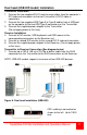


14 CrystalView DVI Mini Installation and Operations Manual
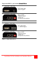
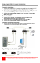
When all cabling is in place, power up the system in the following
recommended sequence:
1. Monitor(s)
2. Receiver unit
3. Transmitter unit
4. Computer
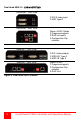
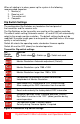
Dip Switch Settings
The configuration Dip-Switches are located on the front panel of
the transmitter and the receiver units.
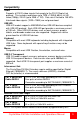
The Dip-Switches on the transmitter are used to set the monitor resolution.
The default switch setting (Automatic control - #1 and #2 Off) will automatically
adapt to the remote monitor resolution. The default setting should only be
modified if the cable length goes to or beyond the specified limits or the image
quality is not satisfactory.
Switch #4 selects the operating mode; standard or firmware update.
Switch #4 must be OFF (down) for standard operation.
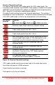
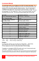
Transmitter Dip-switch settings
DIP
Switch
Position
Function
= Switch down = Switch up = Switch not used
Monitor Resolution: Automatic adjustment (Default)
Monitor Resolution: up to 1280 x 1024
Monitor Resolution: larger than 1280 x 1024
Configuration for Maximum Distance transmission,
Independent of Monitor Resolution
Send stored DDC information to CPU (Default setting)
Allow reading of the DDC information from the monitor
Reset and send only the factory default DDC information
Standard Operation mode: Standard operation (Default)
Dip-Switch 4 must be in the “OFF” (down) position during
normal operation
Test operation mode: Firmware update
Set only during Firmware Update, if required
Figure 9. Transmitter Dip switch settings