CrystalView Extreme LAN Extender INSTALLATION AND OPERATIONS MANUAL Part Number CRK-1DTXT-EX45/A1 10707 Stancliff Road Houston, Texas 77099 Phone: (281) 933-7673 WWW.ROSE.
Limited Warranty Rose Electronics warrants the CrystalView Extreme to be in good working order for one year from the date of purchase from Rose Electronics or an authorized dealer. Should this product fail to be in good working order at any time during this one-year warranty period, Rose Electronics will, at its option, repair or replace the Unit as set forth below. Repair parts and replacement units will be either reconditioned or new. All replaced parts become the property of Rose Electronics.
FCC/IC STATEMENTS, EU DECLARATION OF CONFORMITY FCC Radio Frequency Interference This device complies with Part 15 of the FCC rules; operation is subject to the following two conditions: 1. This device may not cause harmful interference 2. This device must accept any interference received, including interference that may cause undesired operation.
Table of Contents Contents Page # Disclaimer ...................................................................................................... 1 System Introduction ....................................................................................... 1 Features ......................................................................................................... 2 Package Contents .........................................................................................
INTRODUCTION Disclaimer While every precaution has been taken in the preparation of this manual, the manufacturer assumes no responsibility for errors or omissions. Neither does the manufacturer assume any liability for damages resulting from the use of the information contained herein. The manufacturer reserves the right to change the specifications, functions, or circuitry of the product without notice.
Features Supports HD video with resolutions up to 1680 x 1050 Supports USB 2.0 (high-speed / 480 Mb/s), USB 2.0 and 1.1 (Full-speed / 12 Mb/s, and USB 2.0 and 1.1 (Low-speed / 1.5 Mb/s Extend your workstation to any location on your corporate LAN or a point-to-point connection between the transmitter and receiver units. Point-to Point max CATx cable length of 330 feet (100M).
Package Contents Transmitter unit Receiver unit 5V, 3A power adapter (Transmitter) 24V, 1A power adapter (Receiver) USB Type A to Type B cable (6 ft) DVI cable (male to male- 5 ft) Product Manual Additional Installation Items Computer with DVI-D/DVI-I output USB 1.1 or 2.0 host computer 2-CAT5 UTP cable (Transmitter & Receiver to network) or 1 CAT5 cable (Transmitter to Receiver – Point-To-Point) USB 1.1 or 2.
OVERVIEW System Overview The CrystalView Extreme is a very versatile and flexible system that can be easily and quickly installed. You can position your computer anywhere on your LAN and access it over your network from anywhere you install the matched Receiver. The Transmitter unit will locate the Receiver unit within the network by the MAC address. Once found, you will have full control of the computer over your LAN. The CrystalView Extreme system supports HD video and USB 1.1 and 2.0.
MODELS Models Transmitter – Front View Indicators Pair Status Link Video USB Transmitter – Rear View Connectors DVI-D In Config USB Type B Link Power (+5V / 3A) Receiver – Front View Indicators Pair Status Link Video USB Connectors USB Type A (3) Receiver – Rear View Connectors DVI-D Out Headphone Out Microphone In Config Link Power (+24V / 1A) Figure 1.
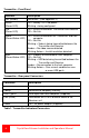
Transmitter - Front Panel Indicator Description Pair (Button) Reserved – (See Appendix C) Status (Green LED) On = Ready / Off = No power / Blinking = being configured Link (Green LED) On = Valid Link between Transmitter and Receiver Off = No Link Video (Green/Amber LED) On = Valid Link between the Transmitter and host computer Off = No Link Blinking = Video is being transmitted between the Transmitter and Receiver Amber = No video source detected Blinking Amber = Invalid resolution detected USB (G
Receiver - Front Panel Connectors Description USB Type A Connection (3) for remote USB devices Indicator Description Pair (Button) Reserved – (See Appendix C) Status (Green LED) On = Ready / Off = No Link Blinking = being configured Link (Green LED) On = Valid Link between Transmitter and Receiver Off = No Link Video (Green/Amber LED) On = Valid Link between the Receiver and the monitor Off = No Link Blinking = Video is being transmitted between the Transmitter and Receiver Amber = No video sou
INSTALLATION System Installation Before installing the CrystalView Extreme, pre-plan the layout of the computer, the Transmitter, the Receiver, and the equipment that will be connected to the Receiver. The Transmitter and Receiver units should be in a location that is easily accessible to your corporate LAN ports. The Transmitter and Receiver units communicate over your LAN using the assigned MAC address. Ensure that your corporate LAN will allow the MAC addresses to properly route over the network.
Receiver installation (Refer to Figure 2) 1. Locate the Receiver unit near the monitor and USB devices. 2. Connect a DVI monitor cable to the DVI-D out connector on the Receiver’s rear panel. 3. Connect your USB and Audio devices to the 3 USB Type A ports on the front panel of the Receiver. Normally these USB ports are connected to a USB keyboard, USB mouse, and a USB Hub. 4. Connect a CAT5* cable (not supplied) from the Receiver’s RJ45 port to a corporate LAN (RJ45) connector. 5.
Connecting USB Devices Up to 13 USB 1.1 or 2.0 devices can be connected to the Receiver unit using USB Hubs. Normally the three USB Type A connectors on the Receiver are connected to a USB Keyboard, USB mouse, and a USB Hub. Installing your USB devices is no different than installing them when connected to a computer. 1. Install the USB device according to the manufactures procedure and any required software to operate the USB device 2. Connect the USB device to the Receiver’s USB ports or a HUB port 3.
TROUBLESHOOTING System Troubleshooting All LEDs on the Transmitter or Receiver are off Check the DC power adapter connection to the Unit Verify there is power at the power source Link LED on the Transmitter and Receiver are off Check the CAT5 Link connections on the Computer, Transmitter, Receiver, and the network information outlets Install a short CAT5 patch cable directly from the Transmitter to the Receiver unit.
No Audio Verify that the CMEDIA device is installed on the host computer (See Installation Verification) Verify that the CMEDIA PNP Audio Device is selected as the default audio device. If not, select it as the default. 1. If the CMEDIA device is enumerated on the host computer as an unknown device, most likely there is a driver conflict. Uninstall all USB device drives. 2. If the CMEDIA device is enumerated as a PNP Audio Device but no audio perform the following: a.
SAFETY Product Safety The CrystalView Extreme extender has been tested for conformance to safety regulations and requirements, and has been certified for international use. Like all electronic equipment, the CrystalView Extreme should be used with care. To protect yourself from possible injury and to minimize the risk of damage to the Unit, read and follow these safety instructions. Follow all instructions and warnings marked on this Unit.
SERVICE AND SUPPORT Maintenance and Repair This Unit does not contain any internal user-serviceable parts. In the event a Unit needs repair or maintenance, you must first obtain a Return Authorization (RA) number from Rose Electronics or an authorized repair center. This Return Authorization number must appear on the outside of the shipping container. See Limited Warranty for more information.
APPENDICES Appendix A – General Specifications Part numbers CrystalView Extreme CRK-1DTXT-EX45/A1 Kit Distance 330 feet (100m) Point-to-point USB Device Support High-Speed (480Mb/s, USB 2.0) Full Speed (12Mb/s, USB 2.0 & 1.1) Low Speed (1.5Mb/s, USB 20. & 1.
Appendix B – Compatibility The CrystalView Extreme is compatible with many graphic cards, monitors, mice, keyboards, monitors, and USB devices. With so many variations of keyboards, mice, and USB devices, Rose Electronics can not guarantee that all peripherals will function properly.
Appendix C – Pairing Transmitter and Receiver The CrystalView Extreme Transmitter and Receiver are paired at the factory to allow communication between them over your LAN. No additional configuration is normally needed. If the Transmitter or Receiver unit needs to be paired to another Transmitter or Receiver, perform the below steps to pair the Transmitter and Receiver units. 1. Disconnect the Transmitter from the host computer and network. 2. Disconnect the Receiver from the network. 3.
NOTES 18 CrystalView Extreme Installation and Operations Manual
10707 Stancliff Road Houston, Texas 77099 Phone: (281) 933-7673 WWW.ROSE.