
Instruction manual


OVERVIEW
4
Orion Installation and Operations Manual
System Overview
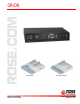
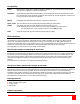
The Orion system consists of the main Orion unit configured with the CPU and CON modules for your application
(CATx or Fiber). Each CPU port connects to a CATx or Fiber transmitter using a CATx or fiber cable.
Each CON port connects to a CATx or Fiber receiver using a CATx or fiber cable.
The versatility of the Orion unit makes it easily
adaptable to your system environment. It can
be configured for a KVM switch where each
user can connect and control any connected
computer.
In the KVM switch mode, a unique feature
called “Partner Viewing” allows a console user
to share the active display content on one or
more displays.
Another feature is the “Follow Me” feature.
This allows other displays to follow every action
made by the console user.
In the Crosspoint switch mode, up to 32 video
sources can be switched to 16 video outputs.
You can switch a video source to 1 output or
16 outputs.
Each CPU input and CON output must connect
to an extender transmitter and extender
receiver. Rose Electronics offers a wide variety
of transmitters and matching receivers to
handle your specific application:
Single, dual, and quad head DVI-D video
models
Local access models
Serial and audio models
CATx or Fiber models
4x USB 2.0 transparent ports for compatible
USB 2.0 peripherals
The installation, configuration, and operation
for each of the different modes are explained in
the appropriate manual section for the
application the Orion unit is going to be
configured for.
Synchronized switching
The Orion unit can be set-up to control the switching features of other Orion units. When the master unit is switched
to a selected CPU port, all other Orion units configured for synchronization will also switch to that CPU port. The
main unit is assigned a unique IP address compatible with the existing network. The main unit is then connected to
the network via a network cable. The master unit’s IP address is entered into the secondary units that will be
switched via the main unit. See Appendix G for installation and OSD configuration instructions.
Fiber CATx
Transmitter Transmitter
Fiber CATx
Receiver Receiver