FJ3 Installation Manual FuelFocus™ FMS System
Table of Contents 1 Introduction ............................................................................................................................. 5 1.1 Purpose............................................................................................................................. 5 1.2 System Overview .............................................................................................................. 5 1.3 Components Overview ......................................................
11.1.1 Capturing Odometer and Engine Hours Information ................................................. 32 11.1.2 Vehicle Data Collection (VDC) - Option .................................................................... 32 11.1.3 Vehicle Speed Sensor (VSS) ................................................................................... 32 11.2 Appendix B: CAN Bus Data Connectors ......................................................................... 35 11.2.1 Vehicle OBD-II Connector J1962 .........
Important Notice Roseman cannot guarantee the RF Vehicle ID Box installation techniques discussed herein are complete and effective on every make, model and year of vehicle and equipment now in the marketplace, or in the future. At times vehicle manufacturers make changes to the engine computer (ECU/ECM), wiring and/or electronics, with new model years and during mid-year production. After-market accessories may also impact the installation of the FJ3 RF Vehicle ID Box.
1 Introduction 1.1 Purpose This FuelFocus® Vehicle Subsystem Installation Manual instructs how to install the Modular Fleet Journal Type 3 (FJ3). Review this manual prior to installing the FJ3. Incorrect installations may cause the system to malfunction. Read this entire manual before your first installation. 1.2 System Overview The Roseman FJ3 is the main component of the Roseman FuelFocus® FMS System in the vehicle.
1.3.1 Modular Fleet Journal (FJ3) The FJ3 is the main component of the Fleet Journal system installed in the vehicle. It stores the vehicle usage data, which includes the start and end times of a trip, beginning and ending odometer readings, maximum speed and more. This provides the fleet manager data of the use of all fleet vehicles. The FJ3 data automatically transfers the data to the FMS application via the ICU/WAF when within approx. 300 feet of the antenna (line of sight).
1.4 Required Tools The following tools are recommended to complete the installation procedures: • • • • • • 1.5 Screwdrivers Solder equipment (if not crimping) Crimping tool Wire stripping tool Drill with 1/8" drill bit Heat gun (for heat-shrink insulation) Required Materials The following materials are required to complete the installation procedures: • • • • • • • • 1.6 Two conductor twisted pair cable 18 - 20 AWG with foil shield and drain wire Wire terminals. Do not use Scotch Locks.
2 Installation Follow the installation instructions detailed in the following sections. Note 2.1 When performing wiring procedures, follow the instructions in Wiring Instructions on page 7. Installation Considerations Before mounting the FJ3 and SVID, determine the best place to install. Consider the following four basic recommendations: • Weather/water Protection – Select a weather-protected location. The FJ3 is not waterproof.
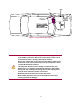
FJ3 Figure 1 Typical Vehicle Wire Routing Do not use an electric drill or any other electrically powered tools within 3 feet of the filler neck or fuel tank, as this area is considered a Class I, Group D hazardous location. Do not use a heat gun or any other heating device within 3 feet of the filler neck or fuel tank as this area is considered a Class I, Group D hazardous location. The Fuel Inlet Antenna and its wiring are intrinsically safe.
3 FJ3 Installation 3.1 Mount the FJ3 1. After reviewing the recommendations listed in 2.1 “Installation Installation Considerations”, mount the FJ3 as follows: • If possible, mount it on the same side of the vehicle as the filler neck. • For a passenger car, the FJ3 can be mounted under the dashboard or in the trunk, provided that the unit is at least 3 feet from the filler neck. • For a truck or bus, the FJ3 can be mounted inside the vehicle's electric enclosure. 2.
Figure 2 FJ3 Mounting and Power Diagram 11
3.3 Connect the RF Antenna The RF Antenna is connected by threading the Antenna connector to the WAF RF jack on the FJ3. 3.4 Mount the RF Antenna The RF Antenna is mounted by removing the protective layer from the adhesive tape and attaching to the vehicle windshield. The same location can be used near the rear window if desired. Note: Clean the windshield before mounting the antenna. In busses, the RF Antenna can be mounted in the sign compartment area, if it is made of fiberglass.
4 Wiring VSS or Pulse Vehicles 4.1 Locating the VSS (Vehicle Speed Signal) The VSS or VSO (Vehicle Speed Output) usually originates near the transmission output shaft. From there it travels to the engine control computer, speedometer and the cruise control computer. Pick a location to tap the circuit near the engine control computer interface, reducing risk of incorrect data due to ignition noise. Also, as with any electronic accessory, a good ground connection is necessary.
Figure 3 FJ3 Wiring Diagram for Speed Pulse 14
4.2.4 Engine Hours To record engine hours, run a single wire from the oil pressure sensor (or any other sensor that is at a continuous "high" state while the engine is running), to the “VSS” input on the FJ3.
5 FJ3 Wiring Diagram for Engine Hour Meter Wiring CANBUS (OBDII) Vehicles 5.1 Connect the Ignition Switch to the FJ3 1. Run a wire from the vehicle ignition switch or any “Key Hot” source (or start/stop button on some hybrid models) to the DC-EO terminal on the FJ3. 2.
5.2.1 Connect the FJ3 to an OBD II Connector (Light Duty Vehicle) If the vehicle has an OBD II connector, perform the following (if not using the AW OBDII harness): 4. Run a twin wire cable from the vehicle connector to the FJ3. 5. Connect the FJ3 CAN_H pin 12 to pin 6 of the OBD II connector. 6. Connect the FJ3 CAN_L pin 2 to pin 14 of the OBD II connector.
Figure 6 :Wiring Diagram for FJ3 with CANBUS OBDII With 2 CAN BUS for Light Duty Vehicles 18
5.2.2 Connect the FJ3 to a 9-pin J1939 Connector (Heavy Duty Vehicle) If the vehicle has a 9-pin Deutsch plug, perform the following (if not using the AW J1939 harness): 1. Run a twin-wire cable from the vehicle connector to the FJ3. 2. Connect the CAN_H Black wire pin 3/C of the Deutsch connector to the FJ3 point CAN_H pin 12. 3. Connect the CAN_L White wire pin 4/D of the Deutsch connector to the FJ3 point CAN_L pin 2.
5.2.3 Connect the FJ3 to a 3 pin J1939 Connector (Heavy Duty Vehicle) If the vehicle has a 3-pin Deutsch connector, perform the following (if not using the AW 3-pin harness): 1. Run a twin-wire cable from the vehicle connector to the FJ3. 2. Connect the CAN_H pin B of the Deutsch connector to the FJ3 point CAN_H pin 12. 3. Connect the CAN_L pin A of the Deutsch connector to the FJ3 point CAN_L pin 2. 4. Connect the ground pin C of the Deutsch connector to the FJ3 point BATT (-) pin 1.
6 Wiring J1708 Vehicles 6.
). Note 6.2 FJ3 does not function properly if an ignition On/Off wire is not connected. FJ3 goes into Sleep mode 30 min after turning off the ignition. Connect J1708 Data wires to the FJ3 The instructions for this procedure depend on the type of the connector equipped with the vehicle – whether it is a J1708 CAB9 (9 pin) connector or a J1708 CAB (6 pin) connector. The following sections provide instructions for both types of vehicles.
Figure 9: Wiring Diagram for FJ3 to J1708CAB9 (9 pin) connector 23
6.2.2 Connect the FJ3 to the J1708 CAB Connector If the vehicle has a 6-pin Deutsch connector, perform the following: 1. Run a twin-wire cable from the vehicle connector to the FJ3. 2. Connect the J1708 Data link (+) wire from pin A of the Deutsch connector. 3. Connect the J1708 Data link (-) wire from pin B of the Deutsch connector.
7 Completion of Installation 7.1 Verify Installation Upon completing installation, verify that the GREEN LED on the FJ3 is blinking every second. This indicates good power and grounding. There are three indicator LEDs on the FJ3 (see Error! Reference source not found.
8 Fueling Options • Hardwired FIA Adaptor - P/N: RID-EM-02 • SVID - P/N: RID-IN-54 Both options require a FIA Fuel Intel Antenna ([P/N RVC-XX –XX] 8.1 Hardwired Fuel Inlet Antenna Wire Adaptor HW FIA Wire Adaptor – part nr: RID-EM-02 Installation Instructions: FCC Compliance and Safety FCC ID: 2AKAM2288 This device complies with Part 15 of the FCC Rules.
To install the Hardwired FIA: 1. Select a fuel inlet antenna diameter to fit the vehicle’s fuel tank inlet. 2. Install it using p-clamps, mountable wire ties, silicone adhesive, etc. 3. Make sure the fuel inlet antenna cable is long enough to reach the location where the FJ3 will be installed. Note If necessary, the cable may be extended.
Velcro adhesive FIA Wire Connections Make sure the wires are plugged in side-by-side into the connector. Press down on the orange tabs to insert or release the wires. 8.1.1 Troubleshooting If the Hardwired FIA wire adapter does not work, do the following: 1. Use the Programmer to try read/verify the FJ3 2. If you cannot read/verify it, ensure that the FIA ring is good and correctly connected. 3. If possible, check the FIA with an Ohm meter, it should read around 50 Ohm, if not replace the FIA. 4.
9 Connecting the [Optional] passive GPS Tracking Device to the FJ3 • When the passive GPS device is connected to the FJ3, it tracks the location of vehicles from “Key On” to “Key Off”. • Each “Key On to Key Off” is a “drive” that is saved in the FJ3 until it can be uploaded to the FJ3 WAF or VDC antenna once within 300’ of it. (Line of sight). • The FJ3 can store hundreds of “drives” internally until uploaded.
10 Driver ID [Optional] 10.1 Connecting the Driver ID To identify the driver of the vehicle, connect the Tag Reader with cable to the Driver ID and to the Dallas connector in FJ3. Figure 13: Connecting the Driver ID reader to the FJ3 10.2 Installing the Driver ID Reader [Tag Reader] Note: Place the Tag reader on the dashboard so that the Dallas key can be easily read. 1. Wire the Tag Reader cables to the FJ3 – see section Error! Reference source not found. REF _Ref462743756 \h \* MERGEFORMAT Error! Ref
Figure 14 COM Cable CBL-9000-023-A 5. Connect the Reader Cable ACC-CB-B7 to the Driver ID Reader. Figure 15 Reader Cable ACC-CB-B7 Important: The Driver ID Reader should be bright red after connecting and installing it correctly. If there is a faint green light in the center of the Reader, this indicates that the Reader is not correctly installed. All the connectors should slide in smoothly, do not force them.
11 Appendices 11.1 Appendix A: Capturing Vehicle Data 11.1.1 Capturing Odometer and Engine Hours Information If the FJ3 is to record the vehicle's odometer, you will need to obtain a pulse relevant to the vehicle’s speed. You can accomplish this either by utilizing an Odometer Adaptor or by receiving electronic pulses from the vehicle speed sensor (VSS) output.
11.1.3.2 Using a Multi-Meter to Measure Frequency (Hz) This is the easiest way to measure the speed signal without the use of an O-scope, but watch out for some things. The meter may give incorrect readings at rest. The meter uses A/C coupling to measure frequency, so it may try to measure noise to determine its frequency. It is most important to measure frequency while the vehicle is moving. The frequency increases proportionately to vehicle speed.
Figure 17 Dual Electronic Adaptor 11.1.3.5 Reed Type Mechanical Adaptor A mechanical pulse Transducer (or taxi Tap) is required if the vehicle utilizes a mechanical cable between the dashboard speedometer and the transmission. Try to order the sensor with an 18 AWG shielded cable of sufficient length to reach the ID Box without splicing.
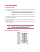
11.2 Appendix B: CAN Bus Data Connectors 11.2.1 Vehicle OBD-II Connector J1962 Figure 19: Car Diagnostic Connector (female) Pin No.
11.2.2 SAE J1939 Data Interface Connector Figure 20: SAE J1939 Model 1708CAB9 11.2.3 3 PIN J1939 Data Interface Connector Figure 21: 3-pin Deutsch J1939 DT06-3S-E008 Pin No.
11.3 Appendix C: J1708 Data Connectors 11.3.
11.4 Appendix H: The FCC Wants You to Know This equipment has been tested and found to comply with the limits for a Class B digital device, pursuant to Part 15 of the FCC rules. These limits are designed to provide reasonable protection against harmful interference in a residential installation. This equipment generates uses and can radiate radio frequency energy and, if the equipment not installed and used in accordance with the instructions, may cause harmful interference to radio communications.