
Installation Manual


13
4 Wiring VSS or Pulse Vehicles
4.1 Locating the VSS (Vehicle Speed Signal)
The VSS or VSO (Vehicle Speed Output) usually originates near the transmission
output shaft. From there it travels to the engine control computer, speedometer and
the cruise control computer. Pick a location to tap the circuit near the engine control
computer interface, reducing risk of incorrect data due to ignition noise. Also, as with
any electronic accessory, a good ground connection is necessary. Improper
grounding could result in a ground loop condition, which may affect the accuracy of
the unit.
Note
Roseman can provide you with an aftermarket catalog for VSS wire,
its color, and how many pulses per mile for the vehicle.
4.2 Connect speed or hour data to the FJ3
The instructions for this procedure depend on the type of vehicle
To view how to capture vehicle data, refer to the Error! Reference source not f
ound.
Note:
FJ3 will not function properly if an “Ignition On/Off” wire is not
connected to the DC-EO terminal. FJ3 goes into Sleep mode
(Power Save) 30 minutes after ignition off.
4.2.1 Connect the FJ3 an Odometer
There are two possible odometer connections:
▪ Direct from an electronic odometer or a speedometer.
▪ From a mechanical odometer via a Reed type odometer adaptor. Also known as
a pulse transducer or “taxi tap”
Note:
If you are recording the vehicle's engine hours, you may skip this
section and go on to section Error! Reference source not found.
REF _Ref455244593 \h Error! Reference source not found..
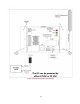
4.2.2 Electronic Odometer or Speedometer
If the vehicle has electronic instrumentation, run a single wire from the vehicle speed
sensor output VSS /VSO + signal to the FJ3 and connect it to "VSS". (See figure 3)
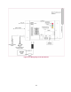
4.2.3 Reed Type Mechanical Adaptor
If the vehicle has a mechanical odometer, and using a Reed type adaptor, run two
wires to the FJ3 and connect it to " BAT(+)" and "VSS". (See figure 3)