
Installation Manual


16
5 FJ3 Wiring Diagram for Engine Hour Meter
Wiring CANBUS (OBDII) Vehicles
5.1 Connect the Ignition Switch to the FJ3
1. Run a wire from the vehicle ignition switch or any “Key Hot” source (or start/stop
button on some hybrid models) to the DC-EO terminal on the FJ3.
2. Refer to:
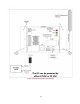
Figure 5: Wiring Diagram for FJ3 with CANBUS OBDII for Light Duty Vehicles
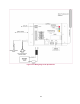
Figure 7: Wiring Diagram for FJ3 with J1939 9-pin Deutsch for Heavy Duty
Vehicles
Figure 8: Wiring Diagram for FJ3 with J1939 Deutsch 3-pin connector for Heavy
Duty Vehicles)
3. The FJ3 needs constant 12- or 24-Volt DC power at the BAT+ and BAT-
terminals
Note
FJ3 will not function properly if an “Ignition On/Off” wire is not
connected to the DC-EO terminal. FJ3 goes into Sleep mode
(Power Save) 30 minutes after turning off the ignition.
5.2 Connect the CANBUS Data wires to the FJ3
The instructions for this procedure depend on the type of vehicle, whether it is a heavy-
duty or a light duty vehicle. Light duty vehicles have an OBD II connector, while heavy
duty vehicles have a SAE J1939 connector. The following sections provide instructions
for both types of vehicles.
To view the connector’s, pin out information, refer to:
Appendix A – Capturing Vehicle Data on pages 41, 42 and 43
Part numbers for AW wire harnesses:
OBDII: CUS-MMU003 (includes J1939 wires for Volvo and Mack trucks)
J1939 9-pin Deutsch (Black): CUS-MMU0092
J1939 9-pin Deutsch (Green): CUS-MMU0092G
J1939 3-pin Deutsch: B-5935 (mostly used for transit buses)