
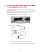
Installation Manual


34
11.1.3.2 Using a Multi-Meter to Measure Frequency (Hz)
This is the easiest way to measure the speed signal without the use of an O-scope,
but watch out for some things. The meter may give incorrect readings at rest. The
meter uses A/C coupling to measure frequency, so it may try to measure noise to
determine its frequency. It is most important to measure frequency while the vehicle
is moving. The frequency increases proportionately to vehicle speed. If the
measurements seem to bounce around, you probably do not have the correct circuit.
11.1.3.3 Using a Multi-Meter to Measure A/C Voltage
This is another way to verify the VSS circuit. This method works poorly with Hall
Sensor outputs. This is because a Hall Sensor’s output varies in frequency but not
amplitude. Most A/C Multimeters display voltage in RMS, which is about 70% of the
peak value of the A/C waveform. Since the peak voltage is constant with a Hall
Sensor, you will see only two readings; the reading while the vehicle is stationary, and
the reading while it is in motion. This is usually enough data to determine if you have
the right circuit.
Using an A/C Multimeter to test a variable reluctance sensor, which are the most
common, will work very well. As with frequency, A/C voltage should fluctuate in direct
proportion to the vehicle speed.
Upon identifying the VSS circuit, then determine the number of pulses per mile that
the sensor emits. To determine the speed and mileage, the FJ3 must know how many
pulses are emitted for a mile traveled. There are only a few different calibration values.
Most Ford and Chrysler products emit 8,000 pulses per mile. GM commonly
uses 4,000 at the control module, and 96000 at the transmission.
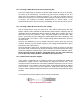
11.1.3.4 Electronic Odometer Adapter
If the vehicle is equipped with an electronic sending unit controlling the dashboard
speedometer, simply connect a wire between the signal line and the FJ3. If the
vehicle's electronic odometer line is also driving additional equipment, such as a cruise
control module or trip computer, there may not be enough signal strength to add the
FJ3 to this line. In this case, you must replace the single sensor with a dual output
sender or add an additional single sender to the unused sender port provided on some
vehicles.
For connection instructions please refer to vehicle manufacturer.
Figure 16 Single Electronic Adaptor