User´s Guide Preliminary edition
User´s Guide First edition Copyright © April 2000 Saab Marine Electronics AB Edition 1. Ref.
Copyright © April 2000 Saab Marine Electronics AB The contents, descriptions and specifications within this manual is subject to change without notice. Saab Marine Electronics AB accepts no responsibility for any errors that may appear in this manual. Trademarks HART is a registered trademark of HART Communication Foundation. LoopRadar is a trademark of Saab Marine Electronics AB. TankRadar is a registered trademark of Saab Marine Electronics AB.
The various warning messages shown in the Users Guide are indicated as follows: ! Caution ! Warning Indicates that incorrect usage may result in personal injury or malfunctioning instruments. Indicates a potentially hazardous situation which could result, if not avoided, in death or serious injury. ! Warning Don´t open lower nut if tank is pressurised or contains hazardous product. Edition 1. Ref.
Contents About this manual....................................................... vi 1 Product Description ...................................... 1-1 1.1 Features ................................................................................ 1-1 1.2 Measurement Principle .......................................................... 1-2 2 Mechanical Installation ................................. 2-1 2.1 Requirements ........................................................................ 2-1 2.
4.3 Volume Calculation ................................................................ 4-5 4.4 Disturbance Echo Handling. .................................................. 4-7 4.4.1 Noise Table ................................................................ 4-7 5 Using the Display Panel ................................ 5-1 5.1 Display Panel......................................................................... 5-1 5.1.1 Display ....................................................................
About this manual The main purpose of Users Guide is to act as guide to installing and operating the Saab LoopRadar. It is not intended to cover service tasks such as changing circuit boards or internal software. Chapter 1 reviews some basic concepts of radar based level gauging. Chapter 2 describes how to assemble a gauge and how to mount it on a tank. Chapter 3 describes the electrical installation.
Product Description 1 Product Description The LoopRadar transmitter uses a non-contact level gauging measurement technique based on the principle of pulsed microwaves. It is loop-powered and easy to install and can be used for many types of level measurement applications. The LoopRadar is safe for humans and has no environmental impact. Propagation of microwaves is virtually unaffected by temperature, pressure or gas characteristics in the tank resulting in excellent measurement stability. 1.
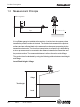
Product Description 1.2 Measurement Principle Pulse sequence 1 ns 1 µs Distance=c* t 2 A LoopRadar gauge is installed at the tank top. It emits short microwave pulses towards the product surface in the tank. The emitted microwaves hit the product surface and are reflected back to the antenna for subsequent processing by the transmitter electronics.
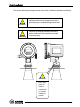
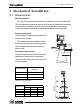
Mechanical Installation 2 Mechanical Installation 2.1 Requirements Mounting position Do not mount the transmitter at the center of the tank or close to the tank wall. This may reduce the measuring range or the accuracy and makes the transmitter more sensitive to disturbing echoes. We recommend that the transmitter is mounted so that the antenna tip is located at least 0.5 m from the tank wall. Socket requirements The antenna tip should be located outside the nozzle (10 mm or more ).
Mechanical Installation Maximum measuring distance Maximum measurement distance is determined by antenna type, dielectric constant of the product and product surface conditions. Please refer to the table below. These values are rough estimates, and are strongly influenced by the measuring conditions.
Mechanical Installation 2.2 Dimensions 172 mm 238 mm 148 mm Ø 52 mm 106 mm Ø 59 mm Ø 154 mm Ø 92 mm 4 Cone antenna Ø 265 mm 346 mm 226 mm Ø 215 mm Ø 140 mm 6 Cone antenna Ø 188 mm 8 Cone antenna Weight LoopRadar(except antenna) 2.5 kg 4 Cone antenna 0.8 kg 6 Cone antenna 1.2 kg 8 Cone antenna 1.8 kg Edition 1. Ref.
Mechanical Installation Flange The LoopRadar gauge is mounted by using a flange according to the following specifications: Ø 54 mm Maximum thickness : 29mm (ANSI Class-150 8 ). 2.3 Tools The following tools are needed for installation of LoopRadar: Hexagon socket screw keys(-4) Adjustable wrench (for locking nut) Pipe wrench (for neck of cone antenna) Screw driver (-) width 3mm 2-4 Edition 1. Ref.
Mechanical Installation 2.4 Mounting the Cone Antenna Transmitter Locking nut 1 Make sure that the following parts are available when installing the gauge. Union nut Caution ! O-ring Set screw Seal Flange Make sure that the PTFE Seal and the O-rings are not damaged. Damaged PTFE Seal or O-ring may cause gas leakage from pressurized tanks. Gasket Nuts and bolts Locking nut 2 Mount the flange on top of the cone plate.
Mechanical Installation 3 antenna adapter into the sleeve and make sure that it fits well into the cone antenna. Secure the antenna adapter with the union nut. Secure the union nut with the set screw. Transmitter Union nut Set screw Antenna adapter Carefully insert the transmitter O-rings ! Sleeve Make sure that the O-ring and the inside of the sleeve are clean in order to avoid gas leakage when using LoopRadar in pressurized tanks. 4 Transmitter Place the gasket on the tank nozzle.
Mechanical Installation 2.5 Installation Hints If obstacles are present in the radar beam, the signal reflected from the product surface may be weaker than the signal from the disturbing object. In this case the LoopRadar may lock on the disturbing object instead of the liquid surface.
Mechanical Installation Correct Wrong Reflector Shoulder 2-8 Edition 1. Ref. No: 307010E Shoulders and Struts Flat surfaces may cause strong false echoes. In order to reduce the impact of such false echoes you can mount a metal plate above the obstacle as shown in the figure.
Electrical Installation 3 Electrical Installation 3.1 Connecting the LoopRadar 1 Remove the front cover. 2 Connect the cable to the terminal block trough the cable entry. Terminal block Ground terminal Cable entry Ground terminal 3 Housing Terminal block Connect the shield to the ground terminal. HART modem 4 250 W Power supply Hand-held communicator Edition 1. Tighten the front cover. Please handle it carefully so that the gasket and window are not removed.
Electrical Installation Example-1 Connection to power supply unit. LoopRadar mounted in non-hazardous area. LoopRadar Power supply > 250 W 4 - 20 mA HART modem Hand-held HART communicator Example-2 Connection to PLC etc. LoopRadar mounted in hazardous area. Non-hazardous area Hazardous area LoopRadar Analog instrument or DCS system (Active) Isolator 4 - 20 mA HART modem Hand-held HART communicator 3-2 Edition 1. Ref.
Electrical Installation 3.2 Cables Cable Use shielded twisted pair for connection. Cable entry 2 x M20 x 1.5, NPT 1/2 " (cable diameter 5-9 mm) 3.3 Load Minimum load for HART 250 W Maximum load (Non-Ex) 810 W Maximum load (Ex) 620 W 3.4 Power supply Supply voltage (Non-Ex) 18 36 VDC Supply voltage (EX) 18 30 VDC IS parameters Ui=30 V, Ii=110 mA, Pi=825 mW, Li=0, Ci=see certificate 3.5 Grounding The terminal must be connected to ground before it is connected to other equipment. Edition 1.
Electrical Installation 3-4 Edition 1. Ref.
Transmitter Setup 4 Transmitter Setup The LoopRadar can easily be installed by using one of the following tools: LoopRadar Display Panel. (See chapter 5 for further information). PC Setup Software. (In preparation). HART Handheld Communicator (Device Descriptor in preparation). Installing a Loopradar transmitter includes the following tasks: Configuration Analog Output parameters Volume calculation settings Advanced settings (for example disturbance echo handling) Edition 1. Ref.
Transmitter Setup 4.1 Configuration 4.1.1 General Settings Output Parameter Measurement value to be shown on the Display and Analog Output Measurement Unit Measurement unit, meter or feet. Antenna Type 4", 6" and 8" Cone are available. 4.1.2 Basic Tank Geometry Specify the following parameters: Tank height R The distance from LoopRadar Reference Point to the tank bottom. The LoopRadar Reference Point is defined as the underside of the flange.
Transmitter Setup 4.1.3 Advanced Tank Geometry Min. Level Offset C The C distance is used to extend the measurement range beyond the Zero Level Reference Point down to the tank bottom. C is defined as the distance between the Zero Level and the tank bottom. Set C=0 if you do not want to present negative levels below the Zero Level reference point, or if you use the tank bottom as zero level reference point.
Transmitter Setup 4.2 Analog Output Analog Output Parameter Specify the source parameter for the analog output. Level is the default parameter. Ullage, Volume or Amplitude are also available. Minimum Output Set the measured value that corresponds to 4 mA. Maximum Output Set the measured value that corresponds to 20 mA. Alarm Selection Set the alarm mode for the analog output current when a measurement error occurs. Low: the output current is set to 3.9 mA. High: the output current is set to 22 mA.
Transmitter Setup 4.3 Volume Calculation The LoopRadar offers four methods to calculate the product volume depending on the tank type. For presentation of volume values you can choose cubic meter, gallons, barrels or cubic feet. Predefined Tank Shapes Spherical Tank The volume is calculated by specifying tank diameter. Vertical cylinder Tank The volume is calculated by specifying tank diameter. Horizontal cylinder Tank The volume is calculated by specifying tank diameter and the tank length.
Transmitter Setup Tank Capacity Table In order to obtain more accurate volume calculations you can create a table of level values and corresponding volumes. A maximum of 20 points can be specified. Volume V4 V3 V2 V1 Level L1 L2 L3 L4 Between the points linearly interpolated values are calculated. At least two points must be entered for the Tank Capacity Table.
Transmitter Setup 4.4 Disturbance Echo Handling. When disturbing echoes appear in the approved measuring range they can be filtered out by setting up a Noise Table. 4.4.1 Noise Table A Noise Table adjusts the threshold level at various parts of the measurement range. By setting the threshold level to an appropriate value the disturbing echo will be suppressed by the transmitter. A Noise Table is defined by ullage points and signal amplitude threshold values. A maximum of 10 points can be specified.
Transmitter Setup 4-8 Edition 1. Ref.
Using the Display Panel 5 Using the Display Panel The Display Panel can be used for configuration of the LoopRadar transmitter as well as for viewing tank data. The keys allow you to navigate through the different menus and to enter desired values for various parameters. 5.1 Display Panel LCD Keys 5.1.1 Display Bar graph, measured data and measuement unit are displayed during normal operation. The last measured value flashes on the display when the gauge is in search mode.
Using the Display Panel 5.1.2 Keys Bar graph Measured value Measurement unit 5-2 1. ENT (ENTER) Press the Enter key to change from measurement mode to configuration mode. You can also use this key to move from the main menu to various sub menus. By pressing the Enter key the cursor can be moved from one digit to the other when entering a new parameter value. 2. ESC (ESCAPE) Press the Escape key to change from configuration mode to measurement mode.
Using the Display Panel 5.2 Basic Key Parameter List By using the Display Panel keys you can make a complete configuration of the LoopRadar. The various settings are grouped into seven main menus: [1--] Configuration Basic configuration of tank dimensions, antenna type and output parameter. [2--] Analog Configuration of analog output signal. [3--] Volume Specification of method for volume calculations. [4--] Calibration Only for service actions. See Appendix 1 for further information.
Using the Display Panel 7LWOH 0HQX &RGH 92/80( 3DUDPHWHUV 6XE 0HQX 6XE 3DUDPHWHU ,QSXW ,QSXW 9DOXH 5DQJH 1RW &DOFXODWH > @ 9HUWLFDO &\ OLQGHU /LQHDULVDWLRQ 6HOHFWLRQ > @ 6SKHULFDO +RUL]RQWDO &\ OLQGHU 8VHU 7DQN 7DEOH /LQHDULVDWLRQ 3RLQW 1XPEHU ,QSXW > @ WR > @ /HYHO 3RLQW > @ > @ WR P > @ 9ROXPH 3RLQW > @ > @ WR 'HOHWH $OO > @ ([HFXWH E\ 'LDPHWHU > @ WR P /HQJWK > @ WR P 2IIVHW /HYHO > @ W
Using the Display Panel 5.3 Navigating the Display Panel Menus Measurement Mode Measuring Data ENT Configuration Mode ESC Main menu CONFIG [1--] Analog [2--] xx [x--] Service [7--] Press the ENT key to switch from measurement mode to configuration mode. Press the ESC key to return to measurement mode. Use the and the Meas. Mode keys to increment menu number. Measuring Data ENT Config.
Using the Display Panel 5.4 Configuration Output parameter 1. Choose sub menu [1-1]. 2. Choose one of the following parameters to be displayed on the panel: 0: Level, 1: Ullage, 2: Volume (%), 3: Current, 4: Amplitude. Antenna type 1. Move to sub menu [1-2]. 2. Choose one of the following antennas: 0: 4 inch Horn Antenna. 1: 6 inch Horn Antenna. 2: 8 inch Horn Antenna. Measurement Unit 1. Choose sub menu [1-3]. 2. Choose one of the following options: 0: meter. 1: feet. Tank Distances 1.
Using the Display Panel Example-1 To set the tank height R to 6.275m do the following: .H\ 'LVSOD\ P 0HDVXULQJ /HYHO P 1RUPDO RSHUDWLRQ PRGH (17 > @ 0DLQ PHQX QXPEHU &RQILJXUDWLRQ PRGH (17 > @ D D > @ > @ D > @ D (17 > @ 'HIDXOW YDOXH (17 ³ ´ IODVKLQJ D ò (17 ò 3XVK WLPHV ¶ ò (17 >; ;@ 6XE PHQX QXPEHU 0DLQ PHQX QXPEHU D ò (17 ¶ ò (17 ¶ (17 (6& (6& > @ (6&
Using the Display Panel 5.5 Volume Calculation Tank Type 1. Choose sub menu [3-1] to specify calculation method. 2. Choose one of the following options: 0 No volume calulation is performed. 1 Volume calculation is based on the shape of a Vertical Cylinder. 2 Volume calculation is based on the shape of a Spherical tank. 3 Volume calculation is based on the shape of a Horizontal Cylinder. 4 Volume calculation is based on a table of level values and corresponding volumes.
Using the Display Panel Example-2 To set the second Volume point to 2345.67m3 do the following: A volume point can be set from 00000.00 to 99999.99. .H\ 'LVSOD\ 0HDVXULQJ /HYHO P 1RUPDO RSHUDWLRQ PRGH (17 > @ D ò (17 > @ 9ROXPH 0DLQ PHQX > @ > @ 9ROXPH SRLQW 6XE PHQX > @ 9ROXPH SRLQW D (17 > @ 9ROXPH SRLQW 'HIDXOW YDOXH (17 ³ ´ LV IODVKLQJ D ò (17 3XVK WLPHV D ò (17 D ò (17 3XVK WLPHV D ò (17 3
Using the Display Panel 5.6 Setting up the Analog Output Output parameter 1. Choose sub menu [2-1]. 2. Choose one of the following parameters as source signal for the Analog Output: 0: Level, 1: Ullage, 2: Volume (%), 3: Amplitude. Output range 1. Choose sub menu [2-2] to enter the Minimum Output value corresponding to the Analog Output value 4 mA. 2. Choose sub menu [2-3] to enter the Maximum Output value corresponding to the Analog Output value 20 mA. Setting up the Alarm Mode 5-10 1.
Using the Display Panel 5.7 Disturbance Echo Handling 5.7.1 Setting up a Noise Threshold Table If the transmitter has locked to a disturbing echo you can create a Noise Threshold Table in order to suppress the disturbing echo: 1. Do the following to check where the disturbing echo is located and the corresponding radar signal amplitude: 1. Choose sub menu [1-1] and set the Output Parameter to Ullage. 2. Note the Ullage value. 3. Choose sub menu [1-1] and set the Output Parameter to Amplitude. 4.
Using the Display Panel Example. A disturbing echo is located at Ullage=3 m. The signal amplitude of the disturbing echo is 3 dB. The following Noise Theshold Table is created to suppress this echo: Sub menu [6-1]: 4 (4 points in the noise table). Sub menu [6-2]: Point 1: [600]=2.7. Point 2: [601]=2.7. Point 3: [602]=3.3. Point 4: [603]=3.3. Sub menu [6-3]: Point 1: [610]=0 dB. Point 2: [611]=8 dB. Point 3: [612]=8 dB. Point 4: [613]=0 dB.
Technical Information 6 Technical Information System Operating frequency 5.8 GHz 6.3 GHz (USA only) Half-power beam width 4 " Cone antenna: 34 deg 6 " Cone antenna: 22 deg 8 " Cone antenna: 17 deg Measuring range Max. 20 m (65 ') Serial communication HART communication Key switch 4 keys for configuration Display 5 digits LCD and bar graph Power Supply voltage 18..30 VDC(Ex) / 18..36 VDC(Non-Ex) Specification for HART Ripple: 47..125 Hz Vpp=200 mV (measured at 500 ohm) Max.
Technical Information Signal on alarm Hold/Low (3.9 mA)/High (22 mA) Load Minimum load for HART communication 250 ohm. Input Voltage (V) Standard Ex ia Load (Ohm) Accuracy Measured error *) ±10 mm (0.4") Linearity *) ±10 mm (0.4") Repeatability *) ±10 mm (0.4") Ambient temperature effect ±0.01% / 10 K *): Free-space reflection from flat metal surface, ambient temperature 25 °C (77 °F), atmospheric pressure. Environment resistance 6-2 Ambient temperature -40..70 °C (-40..
Technical Information Electromagnetic compatibility Emission: EN 50081-1 Immunity: EN 50082-2 Cable Connection Cable type Shielded twisted pair Cross-section area of cable: 0.2..2.5 mm2, (AWG24..14) Cable entry 2-M20X1.5, NPT 1/2" (cable dia. 5..9 mm) Ground cable Max. 4 mm2 Material Transmitter Case Aluminum Cone antenna 316L stainless steel Sealing parts PTFE, Viton O-ring Certificate and Approvals Hazardous area certification 0518 II 1 G - EEx ia IIC T4.
Technical Information 6-4 Edition 1. Ref.
Troubleshooting 7 Troubleshooting LCD status messages [E--] Normal Operation [E01] Internal Error. Serious error. Please contact service department. [E02] Memory Error. Serious error. Please contact service department. [E03] Receive Error. No measure data. Please contact service [E04] Tank CapacityTable Error. Incorrect setting of Tank Capacity Table. [E05] Noise Table Error. Incorrect setting of noise table. [E99] Searching. Searching for Echo Edition 1. Ref.
Troubleshooting 7-2 Edition 1. Ref.
Index Index A Advanced ............................................................................................................................................ 5-3 Analog ...................................................................................................................................... 5-3, A1-1 Analog Output ............................................................................................................................ 4-4, 5-10 alarm ....................................
Index K Key Parameter List .................................................................................................................... 5-3, A1-1 Keys ................................................................................................................................................... 5-2 L Load .................................................................................................................................................... 3-3 Loop-Power .............................
Appendix 1: Key Parameters Appendix 1: Key Parameters By using the Display Panel keys you can make a complete configuration of the LoopRadar. The various settings are grouped into seven main menus: [1--] Configuration Basic configuration of tank dimensions, antenna type and output parameter. [2--] Analog Configuration of analog output signal. [3--] Volume Specification of method for volume calculations. [4--] Calibration Calibration of analog output range and calibration of level measurements.
Appendix 1: Key Parameters 7LWOH 0HQX &RGH 92/80( 3DUDPHWHUV 6XE 0HQX 6XE 3DUDPHWHU ,QSXW ,QSXW 9DOXH 5DQJH > @ 1RW &DOFXODWH 9HUWLFDO &\ OLQGHU /LQHDULVDWLRQ 6HOHFWLRQ > @ 6SKHULFDO +RUL]RQWDO &\ OLQGHU 8VHU 7DQN 7DEOH /LQHDULVDWLRQ 3RLQW 1XPEHU ,QSXW > @ WR > @ /HYHO 3RLQW > @ > @ WR P > @ 9ROXPH 3RLQW > @ > @ WR 'HOHWH $OO > @ ([HFXWH E\ 'LDPHWHU > @ WR P /HQJWK > @ WR P 2IIVHW /HYHO > @
Saab Tank Control Box 13045 S-402 51 Göteborg SWEDEN Phone: + 46 31 337 00 00 Fax: + 46 31 25 30 22 e-mail: sales.stc@marine.combitech.se Internet: http://www.saab.tankradar.com MFR. TOKIMEC INC. Control Systems Division 2-16-46, Minami-kamata, Ohta-ku, Tokyo 144-8551 JAPAN Phone: + 81 3 3737 8631 Fax: + 81 3 3737 8666 Ref. no. 307010 E. First edition. February 2000.