User´s Guide
Saab TankRadar® Pro User´s Guide Second edition Copyright © September 1998 Saab Marine Electronics AB Edition 2. Ref.
Saab TankRadar® Pro Copyright © March 1999 Saab Marine Electronics AB The contents, descriptions and specifications within this manual is subject to change without notice. Saab Marine Electronics AB accepts no responsibility for any errors that may appear in this manual. Trademarks HART is a registered trademark of HART Communication Foundation Modbus is a registered trademark of Modicon. Pentium is a registered trademark of Intel Corporation.
Saab TankRadar® Pro Contents About this manual ........................................................ vii 1 Introduction............................................................ 1-1 The TankRadar Pro System .......................................................... 1-1 Measurement Principle.................................................................. 1-3 2 Mechanical Installation ......................................... 2-1 Socket Requirements .................................................
Saab TankRadar® Pro Connecting to a TRL2 Bus Interface ............................................ 3-6 Connecting HART devices ............................................................ 3-7 Active output (internal loop supply) .............................................. 3-7 Passive output (external loop supply)........................................... 3-7 Intrinsically safe conditions ........................................................... 3-8 Non-Intrinsically safe conditions .................
Saab TankRadar® Pro Setting measurement units ........................................................... 4-7 Installing a Pro Transmitter .......................................................... 4-8 Setting a general amplitude threshold ........................................ 4-26 Creating a customized noise threshold table.............................. 4-26 Registration of False Echoes ..................................................... 4-29 Viewing Level Data .......................................
Saab TankRadar® Pro Display Panel.................................................................................. 7-3 Analog Outputs .............................................................................. 7-3 8 Troubleshooting .................................................... 8-1 Display Panel Error Messages ...................................................... 8-2 User Input Errors .......................................................................... 8-2 Internal Software Errors ......
Saab TankRadar® Pro About this manual This User´s Guide provides information about mechanical and electrical installation of a Saab TankRadar Pro gauge. It also describes how to start up and configure the gauge. The main purpose of the book is to act as guide to installing and operating a TankRadar Pro gauge. It is not intended to cover service tasks such as changing circuit boards or internal software. Chapter 1 reviews some basic concepts of radar based level gauging.
Saab TankRadar® Pro viii Edition 2. Ref.
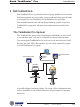
Saab TankRadar® Pro Introduction 1 Introduction Saab TankRadar Pro is a powerful radar level gauge suitable for non-contact level measurements in process tanks, storage tanks and other types of tanks. It is designed for easy installation and maintenance free operation. The modular hardware and software design makes it possible to specify a TankRadar Pro gauge that will meet your requirements now and in the future. The TankRadar Pro System The TankRadar Pro gauge offers a high degree of flexibility.
Saab TankRadar® Pro Introduction RTG 40 Analog Instrument Display Panel HART Interface Analog Instrument Control System 7 8 9 4 5 6 1 2 3 Hand Held HART Communicator If HART technology is used you can configure and monitor measurement data via a hand held communicator or a PC. For stand-alone systems, or as a complement to a PC or a control system, you can monitor level data using one or two analog outputs depending on the particular hardware configuration.
Saab TankRadar® Pro Introduction Measurement Principle The Saab TankRadar Pro transmitter sends a microwave signal with a continuously varying frequency towards the liquid surface. When the reflected signal returns to the antenna, it is mixed with the outgoing signal.
Saab TankRadar® Pro Introduction urements in tanks with agitators, mixers and other disturbing objects. Saab´s echofixer provides a technique to adapt measurements to various situations, by using information from previous measurements. To further improve measurement accuracy, Saab TankRadar Pro can utilize the benefits of Saab´s Fast High Accuracy Signal Technique™ (FHAST™).
Saab TankRadar® Pro Mechanical Installation 2 Mechanical Installation For optimum measurement performance the TR Pro gauge should be mounted according to the socket requirements and the free space requirements illustrated below. Socket Requirements In order to allow the microwaves to propagate freely, the socket dimensions should be kept within the specified limits for different antenna sizes.
Saab TankRadar® Pro Mechanical Installation Free Space Requirements Position the gauge in a way that allows the microwaves to propagate without disturbance from the tank wall, according to the illustration below. Service space (mm): • Cone antenna: 650 • Rod antenna: 700 • Process Seal antenna: 800 • Parabolic antenna: 700 Service space 550 mm Maximum angle: • Cone antenna: 1° • Rod antenna: 3° • Process Seal antenna: 3° • Parabolic antenna: 0.5° Minimum distance (m): • Cone antenna: 0.
Saab TankRadar® Pro Mechanical Installation Dimensions 200 mm 395 mm 150 mm (4” cone antenna) 260 mm (6” cone antenna) 370 mm (8” cone antenna) 92 mm (4” cone antenna) 140 mm (6” cone antenna) 188 mm (8” cone antenna) Tools The following set of tools is needed for installation of a TankRadar Pro gauge: • Screw driver • Adjustable wrench • Dispenser for retaining rings • Allen key • Circlip pliers • Pro multipurpose key Edition 2. Ref.
Saab TankRadar® Pro Mechanical Installation Mounting the Rod Antenna Make sure that all parts are clean and dry when mounted. Tank flange diameter = 50 mm (2) 1. Put a gasket on the socket and insert the antenna. Gasket Loose flange 2. Mount the loose flange and tighten the screws. 3. Insert the wave guide tube into the upper wave guide. Make sure that all parts are clean and dry. O-ring Wave guide tube 4. Place the transmitter on top of the antenna and tighten the nut. Nut 2-4 Edition 2. Ref.
Saab TankRadar® Pro Mechanical Installation Tank flange diameter = 65 mm (3) Flange adapter 1. Carefully center the flange adapter on top of the tank flange. Use gaskets under and above the flange adapter. Flange 2. Insert the antenna into the socket. Mount the loose flange and tighten the screws. 3. Insert the wave guide tube into the upper wave guide. Make sure that all parts are clean and dry. Wave guide tube Nut 4. Place the transmitter on top of the antenna and tighten the nut. 5.
Saab TankRadar® Pro Mechanical Installation Mounting the Cone Antenna - PTFE sealing 1. Mount the flange on top of the cone plate. Make sure that the bottom side of the flange is flat and all parts are clean and dry. 3. Mount the adapter on top of the sleeve. Locking ring Adapter Flange O-ring Wave guide unit Diameter=33 mm Note! No gasket on top of this plate Sleeve 2. Secure the flange with the locking nut. Make sure that the nut fits tightly to the flange. 4.
Saab TankRadar® Pro 5. Carefully fit the flange and the cone antenna on the tank nozzle. Tighten with screws and nuts. Mechanical Installation 7. Place the protection sleeve on the flange. Mount the transmitter head. Check that the guide pins on the adapter enter the corresponding grooves on the upper wave guide. Upper wave guide Protection sleeve Guide pins Gasket Adapter 6. Insert the wave guide tube into the upper wave guide. 8. Proceed with the electrical installation.
Saab TankRadar® Pro Mechanical Installation Mounting the Cone Antenna - Quartz Sealing 1. Mount the flange on top of the cone plate. Make sure that the bottom side of the flange is flat and all parts are clean and dry. 3. Mount the adapter on the sleeve. Locking ring Adapter Flange O-ring Sleeve Note! No gasket on top of this plate 2. Secure the flange with the locking nut. Make sure that the locking nut fits tightly to the flange. 4. Secure the adapter with the locking ring.
Saab TankRadar® Pro 5. Carefully fit the flange and the cone antenna on the tank flange. Mechanical Installation 6. Place the protection sleeve on the flange. Tighten with screws and nuts. Mount the transmitter head. Check that the guide pins on the adapter enter the corresponding grooves on the upper wave guide. Upper wave guide Protection sleeve Guide pins Adapter Gasket 7. Proceed with the electrical installation. Edition 2. Ref.
Saab TankRadar® Pro Mechanical Installation Mounting the Cone Antenna - Process Seal Preparations It is very important that the nozzle surface is flat. The maximum deviation must be within the following specifications as illustrated below (see Installation Instruction Process Seal Doc. no. 9240007-985): d Concave: Ceramic window: d<0.1 mm PTFE window: d<0.5 mm Convex: Ceramic window: d<0.1 mm PTFE window: d<0.5 mm 2-10 Edition 2. d Ref.
Saab TankRadar® Pro Mechanical Installation To mount the antenna do the following: 1. Place a gasket on top of the socket and mount the antenna. Use one of the two gaskets delivered by Saab: • Teflon or • Graphite for temperatures above 250 º C. Note! Use gaskets delivered by Saab. These gaskets are optimized for use with microwave emitting equipment. No other gaskets than Saab original may be used for Process Seal antennas! 2. Put the loose flange on top of the antenna 3.
Saab TankRadar® Pro Mechanical Installation 4. Insert the wave guide tube into the upper wave guide. Wave guide 5. Mount the transmitter head onto the adapter. Wave guide tube Nut 6. Tighten the nut and make sure that the transmitter head fits tightly to the antenna. 2-12 Edition 2. Ref.
Saab TankRadar® Pro Mechanical Installation Torque Attach the flange screws by using the following recommended torque values: Reco mmended To rque (N m) PT FE DIN Flange PN 6 P N 10 P N 16 P N 25 PN40 D N 100 23 11 11 15 15 D N 150 12 15 15 A N SI 150 Psi 300 Psi Flange 4" 11 15 6" 15 10 Ceramic DIN Flange PN 6 P N 10 P N 16 P N 25 PN40 D N 100 69 35 35 45 45 D N 150 36 46 46 A N SI 150 Psi 300 Psi Flange 4" 35 45 6" 46 31 Table 1.
Mechanical Installation Saab TankRadar® Pro Mounting the Parabolic Antenna Flange 1. Mount the flange on top of the antenna feeder. Use the screws and nuts delivered with the unit. Make sure that the guide pin at the bottom side of the flange fits into the corresponding hole on the feeder. See illustration. Guide pin Hole Antenna feeder TRL2 adapter Guide pin 2. Mount the TRL2 adapter on top of the flange and tighten the nuts loosely in order to allow the TRL2 adapter to be rotated.
Saab TankRadar® Pro Mechanical Installation Flange 3. Mount the antenna feeder to the tank nozzle. If necessary, use angular rings (inclination device) to align the antenna within o ±0.5 . The rings can be used if the tank o nozzle flange is horizontal within ±4 . Antenna feeder Angular rings Gaskets Nozzle 4. Mount the parabola onto the lower flange on the antenna feeder. Lower flange Parabola Edition 2. Ref.
Saab TankRadar® Pro Mechanical Installation TCP tube 5. Mount the TCP tube into the TRL2 adapter. TRL2 adapter 6. Mount the transmitter head. Rotate the head and the TRL2 adapter to align the cover locking at the back of the transmitter head with the guide pins. Note! It is very important that the transmitter head is properly aligned to the guide pins. Improper alignment may cause poor measurement performance. Transmitter head Cover Locking Guide pins 2-16 Edition 2. Ref.
Saab TankRadar® Pro Electrical Installation 3 Electrical Installation Identication of Installed Options I II III IV V Approval Power Supply Primary Output Display Panel Secondary Output I Approval C F P X Cenelec FM PTB Other certificates II Power Supply A D 100 - 240 VAC nominal power 24 -48 VDC nominal power III Primary Output 1A 1C 1B 1D 2A Non-IS HART/4-20 mA, active. Non-IS HART/4-20 mA, passive. IS HART/4-20 mA, active. IS HART/4-20 mA, passive.
Saab TankRadar® Pro Electrical Installation Junction Box The standard version is equipped with a junction box that consists of a non-intrinsically safe and an intrinsically safe part. There is also an optional version with two non-intrinsically safe compartments. Flameproof enclosure CENELEC: EExe FM: Explosion proof Primary analog output or serial communication (FM: conduit fitting) Power supply (FM: conduit fitting) 3-2 Edition 2. Ref.
Saab TankRadar® Pro Electrical Installation External Connections Non-Intrinsically SafeJunction Box -EEx e This Junction Box is for non-intrinsically safe connections and power supply. A X1 > 5 4 3 2 EExe 1 1-2 Non-intrinsically safe HART/4-20 mA primary analog output, or TRL/2 Bus 3-4 Power supply input 5 Not connected A Electrical safety ground terminal Note: redundant when the transmitter is grounded according to CENELEC.
Saab TankRadar® Pro Electrical Installation Intrinsically Safe Junction Box - EEx i This Junction Box is for intrinsically safe connections and for connection of the Display Panel. 2
Saab TankRadar® Pro Electrical Installation Alternative Non-intrinsically Safe Junction Box This is the standard intrinsically safe Junction Box (EExi) fitted with an alternative connector for connection of non-IS output if required.
Saab TankRadar® Pro Electrical Installation Connecting to a TRL2 Bus Interface Use a Field Bus Modem (FBM) for a Pro transmitter equipped with a TRL2 interface. Field Bus Modem Connect to the non-intrinsically safe junction box (EEx e). Junction Box EEx e 1 2 3 4 5 X1 100-240 VAC or 24-48 DC 3-6 Edition 2. Ref.
Saab TankRadar® Pro Electrical Installation Connecting HART devices Active output (internal loop supply) Junction Box EEx e For Pro gauges with active output a hand-held terminal or a HART modem can be connected as follows: Input impedance <300 Ohm 1 2 3 4 5 X1 7 8 9 4 5 6 1 2 3 100-240 VAC or 24-48 VDC Passive output (external loop supply) A hand-held terminal or a HART modem should not be connected directly across an external power supply.
Saab TankRadar® Pro Electrical Installation Intrinsically safe conditions A hand-held HART communicator can be connected in the hazardous area. The HART interface must be connected via a zener barrier in the safe area. Hazardous Area Non-Hazardous Area RTG 40 HART interface Zener barrier Hand held HART communicator 7 8 9 4 5 6 1 2 3 Analog instrument and/or DCS system Non-Intrinsically safe conditions RTG 40 HART interface 3-8 Edition 2. 7 8 9 4 5 6 1 2 3 Ref.
Saab TankRadar® Pro Electrical Installation Connecting the Display Panel The Display Panel is intrinsically safe and may only be used when permanently mounted directly on the enclosure with two separate grounding wires.
Saab TankRadar® Pro Electrical Installation Cables Depending on local requirements, cable glands or explosion proof conduits must be used for connection to the nonintrinsically safe junction box (EEx e). For the connection to the instrinsically safe junction box (EEx i) use cable glands with integral shield connection for cable diameter 6-12 mm or conduit. Use shielded instrument cable 0.5 mm2 (AWG 20) for analog outputs and serical communication.
Saab TankRadar® Pro Electrical Installation System Overview Schematic illustration of Pro transmitter connections Display Panel Connect the intrinsically safe Display Panel to terminals 5, 6 and ground in the intrinsically safe (EExi) junction box. Main Board Analog Outputs Level Display Panel Interface mm GRPH ITEM (DI40) X2 Extra Analog Output (XA40 + IS40) X3/X6 X6 X5 Connect the primary analog output to terminals 1 and 2.
Saab TankRadar® Pro Electrical Installation Internal Connections Intrinsically Safe (EEx i) 2 6 3 5 4 4 5 3 X7 1 X6 X4 X3 Non-Intrinsically Safe (EEx e) X5 2 1 X1 X2 Power Supply Option Description Board A 100 - 240 VAC AC40 D 24 - 48 VDC DC40 X3 X4 DC40 AC40 X4 X4 D PO+ 1 PO- 2 L+ 3 L- 4 5 A X1 Display Panel IS Gnd Board 0 No Display Panel NA P Display Panel DI40 DI40 DPS DP+ SO- P X6 Description X7 X7 Option SO+ X5 POPO+ 6 5 4 3 2 1 X2 3-12
Saab TankRadar® Pro Electrical Installation Primary Output Description Board 1A Non-intrinsically safe HART/4-20 mA, active. HM40+IS40 Non-intrinsically safe HART/4-20 mA, passive HM40 TRL2 Bus 2A HM40 1C IS40 1A TM40 X4 2A HM40 X3 X3 1C TM40 X3 Option X3 Non-Intrinsic Safety (EEx e) PO+ 1 PO- 2 L+ 3 L- 4 5 X1 Intrinsic Safety (EEx i) IS Gnd DPS 1D HM40+IS40 Intrinsically safe HART/4-20 mA, passive HM40 HM40 1D HM40 1B Edition 2. Ref.
Saab TankRadar® Pro Electrical Installation Secondary Output Intrinsic Safety (EEx i) Board B Intrinsically Safe 4-20mA active XA40+IS40 Intrinsically Safe 4-20mA passive XA40 DPS D XA40 DP+ SO- X6 X6 D IS Gnd XA40 X7 Description X6 Option SO+ IS40 B X5 POPO+ 6 5 4 3 2 1 X2 Non-Intrinsic Safety (EEx e) Board A Non-intrinsically safe 4-20mA active XA40+IS40 C Non-intrinsically safe 4-20mA passive XA40 XA40 5 C XA40 SOX6 X6 Description X6 Option SO+ A IS40 X5 POPO+
Saab TankRadar® Pro Pro Setup 4 Pro Setup Software The Pro Setup software is an easy to use PC program for configuration of the Saab TankRadar Pro transmitter. It is designed to run under Windows95/NT4.0. It also includes options for viewing tank data as well as options for advanced service. RTG 40 PC Modem It is a simple task to start and configure the TankRadar Pro transmitter.
Saab TankRadar® Pro Pro Setup System Requirements Processor: Pentium Operating system: Windows95/NT 4.0 Memory: 16 MB Hard disk space: 5 MB Installing the Pro setup software To install TankRadar Pro configuration software on your computer do the following: 1 Start Windows and make sure that no applications are running. If you run Pro Setup under Windows 95, upgrade Windows 95 by running the Dcom95.exe upgrade kit. 2 Insert the TankRadar Pro setup disk.
Saab TankRadar® Pro 4 Pro Setup Choose installation directory. Program Files\Saab is the default directory. Click the Browse button if you want to specify another installation directory. Click the Next button. 5. Follow the instructions in the installation wizard. Click the Next button. Edition 2. Ref.
Saab TankRadar® Pro Pro Setup 4-4 6 Specify the Com port and communication protocol you will use to connect the gauge. Com port and protocol can be changed later. 7 Finish the installation. Edition 2. Ref.
Saab TankRadar® Pro Pro Setup Starting the Pro Setup Program Do the following to start Pro Setup: 1 Click the Start button in the Windows95 Task bar. Pro Setup icon Programs menu Start button Note! 2 Open the Programs menu. 3 Open the Saab ProSetup folder. 4 Click the Pro Setup icon. While Pro Setup is running, the Win95 Task Bar contains two buttons named “Pro Setup” and “Saab TankRadar IO Master Server” .The last button refers to a communication program supporting Pro Setup.
Saab TankRadar® Pro Pro Setup Setting a Password You can set a password to prevent unauthorized changes of the transmitter configuration. Then you will have to enter the password in order to obtain access to configuration and service options. You do not need to enter a password for viewing tank data. To set a password do the following: 1 Select Password from the Setup menu. 2 Leave the Password input field blank if no password has been set. 3 Click the Change button.
Saab TankRadar® Pro Pro Setup Logging on to a password protected system. To log on to a password protected system do the following: 1 Select Password from the Setup menu. 2 Enter your password in the Password input field. 3 Click the Log On button. 4 When your password is accepted click the Close button. Setting measurement units 1 Select Measurement Units from the Setup menu. 2 Select the desired units for Level/Ullage, Level Rate and volume. 3 Click the Store button. Edition 2. Ref.
Saab TankRadar® Pro Pro Setup Installing a Pro Transmitter Do the following to install and configure a Pro transmitter: 1 Connect to a TankRadar PRO transmitter. 1 Select New Tank from the File menu in the Main window. 2 Enter a tank name to associate with the tank and click the OK button. Response: the Tank Radar PRO Setup window is opened with the address tab active. 4-8 Edition 2. Ref.
Saab TankRadar® Pro Pro Setup 2 Enter protocol and address data. 1 In the Protocol box specify the protocol that you will use for the serial communication. • Choose HART if your gauge is equipped with an analog output and a HART interface (make sure that the HART interface is correctly installed according to the recommendations for active and passive analog outputs, see Electrical Installation). - or • Choose Saab Modbus if your gauge is equipped with a TRL/2 Bus interface.
Saab TankRadar® Pro Pro Setup 2 Set the communication address. To set a new address you have to know the current address or the Unit ID/Long Address (HART) to establish communication with the gauge. The default address is 0 for HART and 246 for Modbus. To change the address, do the following: 1 Enter the address that is currently stored in the gauge (the default address for a new gauge) into the address field. 2 Click the Read button. Response: the Unit ID/Long Address is displayed.
Saab TankRadar® Pro Pro Setup 3 Select the Start Radar tab 1 Click the Read button. Response: the current settings and the Start Code are displayed. Note! 2 Check that the correct set of available options is displayed. Contact your local representative if you like to add one or more of the following software options: EchoFixer, MET, FHAST filtering or strap table volume calculations. 3 Mark the check boxes that corresponds to available software options that you want to enable.
Saab TankRadar® Pro Pro Setup 5 In the Tank Environment and Presentation Standard tab there are two groups of parameters. In the Environment box mark the check boxes that correspond to the conditions in your tank: Rapid level changes optimizes the transmitter for measurement conditions where the level changes quickly due to filling and emptying of the tank. Turbulent Surface This parameter may be used if the tank e.g. contains boiling products causing a turbulent surface.
Saab TankRadar® Pro Pro Setup restricted to a region close to the tank bottom (Related database register: Full tank detection area, 1516). Do not set this parameter if the bottom echo is not visible. Slow Search 6 This variable controls how to search for the surface if a surface echo is lost. With this parameter set the transmitter starts searching for the surface at the last known position, and gradually increases the width of the search region until the surface is found.
Saab TankRadar® Pro Pro Setup Tank Environment See description of the Tank Environment parameters in the Standard tab. Note! The Tank Environment parameter settings overrides some of the Holding register settings. Tank Obstacles This option is not used in the current version of the Pro application software. 4-14 Edition 2. Ref.
Saab TankRadar® Pro Pro Setup Tank Presentation Level above min distance possible If the surface echo is lost in the vicinity of the antenna, full tank is indicated and searching for the surface echo is limited to a region close to the antenna. Predicting allowed Improves the performance when filling or emptying a tank. Setting this parameter may reduce the time to detect a lost surface echo resulting in better tracking of a moving surface.
Saab TankRadar® Pro Pro Setup solved by changing the mechanical installation. Related database register: DoubleBounceOffset (1522). Slow search See description of the Standard tab parameters. Related database register: SearchSpeed (1524). Double surface Indicates that there are two liquids in the tank resulting in two reflecting surfaces. The upper liquid is must to be partly transparent to the radar signal.
Saab TankRadar® Pro Invalid level is not set if tank is full or empty Pro Setup If the surface echo is lost close to the top or close to the bottom of the tank, the level value full/empty will normally be displayed as “invalid”. Set this parameter to suppress the “invalid“ display. Note! By setting this parameter the analog output will not enter alarm mode for invalid levels close to the tank bottom or close to the antenna. Click the Store button when all settings are finished. Edition 2. Ref.
Saab TankRadar® Pro Pro Setup 4 Select the Configuration tab 1 Click the Read button. Response: the current settings are displayed. 2 In the Tank Geometry box, enter values for Distance Offset (G), Tank Height (R) and Minimum Level Offset (C). The Distance Offset (G) is defined as the distance between the upper reference point and the flange (the flange is referred to as the Tank Radar Pro Reference Point). You can use G to specify your own reference point at the top of the tank.
Saab TankRadar® Pro Pro Setup the distance between the zero level and the tank bottom. Set C=0 if you use the tank bottom as zero reference point. The Hold Off (H) distance defines how close to the TR Pro reference point a level value is accepted. Normally the Hold Off distance does not need to be changed.
Saab TankRadar® Pro Pro Setup 5 Select the Analog Outputs tab 1 Click the Read button. Response: the current settings are displayed. 2 If your transmitter is equipped with a HART® modem select the Analog Out1 tab. (Analog 1 is note available when using TRL2 Bus communication). 3 Select the source to control the analog output. 4 Enter the range values that correspond to the analog output values 4 and 20 mA. 5 Enter the alarm mode, i.e the analog out state on measurement error.
Saab TankRadar® Pro Pro Setup Calibrating the Digital to Analog Converter (DAC) The Digital to Analog Converter (DAC) is factory calibrated. However, if you want to check the calibration by measuring the output current, do the following: 1 Click the Calibrate DAC... button. 2 Read the instruction and the warning. Note! The analog output will be set to fixed current mode. Make sure that control systems connected to the output are not harmed. 3 Click the Set to 4 mA button.
Saab TankRadar® Pro Pro Setup 4-22 5 Click the Set to 20 mA button. 6 Enter the measured output current and click the Store button. 7 Click the Cancel button to close the window and finish the calibration. Edition 2. Ref.
Saab TankRadar® Pro Pro Setup 6 Volume Calculations Pro Setup performs Volume Calculations by using one of two methods: predefined tank shape or strapping table. The strapping table is an optional function. If it is not available a new Start Code can be ordered from Saab Tank Control. To enable Strapping Table select the corresponding option in the Pro Setup/Volume window. To configure the TR Pro Transmitter for volume calculations do the following: 1 Select the Volume tab 2 Select a tank shape.
Saab TankRadar® Pro Pro Setup Ideal tank Use this option if approximation of your tank with an ideal tank shape provides sufficient accuracy. Enter the follwoing parameters: • Tank diameter (or the length if it is a horizontal tank). • “Distance between zero volume and zero level mark”: set this parameter if you do not want zero volume and zero level to match (for example if you want to include volume below the zero level). Strapping table • Enter level and corresponding volume values.
Saab TankRadar® Pro Pro Setup 7 Disturbance Echo Handling Pro Setup offers you powerful tools to handle disturbing echoes. The False Echo tab displays a list of echoes detected by the Pro transmitter. To optimize measurement performance you can register false echoes which are due to disturbing objects in the tank like beams, agitators and heating coils. The Spectra-Threshold tab shows the amplitude of the measured signal along the tank.
Saab TankRadar® Pro Pro Setup Setting a general amplitude threshold 1 Click the Read button General amplitude threshold Response: a spectrum is displayed showing the radar amplitude vs. distance from the gauge to the product surface (ullage). 2 Set the general Amplitude Threshold. Echoes with amplitudes below the general amplitude threshold will be disregarded. Recommended threshold value: Calm conditions: no turbulence, foam or condensation.
Saab TankRadar® Pro Pro Setup Add button To add points to the diagram: 1 Place the mouse pointer in the diagram at the position where you want to add a point to the Amplitude Threshold curve. 2 Click the right-hand mouse button and select Add point, - orclick the Add button in the SpectraThreshold window. Note! The Amplitude Threshold Table displays the position of the currently selected point, not the position of the added point.
Saab TankRadar® Pro Pro Setup The following examples illustrate how the Amplitude Threshold table can be used: Example 1: The amplitude threshold is used to remove the influence from the tank nozzle. Influence from pipe inside the tank Influence from nozzle Example 2: In this example the amplitude threshold is used to filter out weak disturbances close to the tank bottom. By using this technique the risk of locking to a disturbance echo close to the tank bottom is eliminated.
Saab TankRadar® Pro Pro Setup Registration of False Echoes The False Echo function allows you to let the transmitter register disturbing echoes caused by objects in the tank. This makes it possible to detect a product surface close to a disturbance echo even if the surface echo is weaker than the disturbing echo. 1 Select the False Echo tab 2 Click the Read button to update the list of interfering echoes. The right-hand list displays disturbances that was detected by the transmitter.
Saab TankRadar® Pro Pro Setup • Make sure that the level is stable before you register a disturbance echo. A fluctuating level may indicate a temporary disturbance which is not due to an interfering object. • Do not register a disturbing echo if the amplitude is below the general amplitude threshold, see description of the Spectra-Threshold window.
Saab TankRadar® Pro Pro Setup To register interfering echoes do the following: 1 Select an echo from the list of Interfering Echoes. Echo to be registered 2 Click the Add Echo button. Add Echo Response: the echo is displayed in the table of Registered echoes. Registered echo 3 Repeat step 2 until all echoes that you want to register as interfering echoes (see recommendations on the previous page) are added to the left-hand table.
Saab TankRadar® Pro Pro Setup To manually add items to the list of registered disturbing echoes You can manually enter disturbing echoes which are not present in the list of automatically detected echoes. This function can be useful if there are objects below the product surface which can not be detected by the gauge at the time of installation. To manually add echoes do the following: 1 Enter an ullage value in the Location field.
Saab TankRadar® Pro Pro Setup Viewing Level Data To view level data do the following: 1. Start the Pro Setup program. 2. Open a tank file by choosing Open Tank from the File menu or by clicking the Open Tank button. 3. Select the Tank Display option from the View menu, - or click the Display button in the PRO Setup Main window. The contents of this window is continuously updated. You can change measurement units by choosing the Measurement Units option from the Setup menu. Edition 2. Ref.
Saab TankRadar® Pro Pro Setup Service The following options are available from the Service menu: Diagnostics This option allows you to view the TankRadar Pro status registers. Input and Holding Registers You can view the Input registers as well as the Holding registers by selecting the corresponding option from the Service menu. The Holding registers can be edited.
Saab TankRadar® Pro Pro Display Panel 5 Using the Pro Display Panel Operation You can use the Display Panel (DP) for configuration as well as for viewing tank data. The four softkeys allow you to navigate through the different menus, and to select various functions for service and configuration.
Saab TankRadar® Pro Pro Display Panel Adjusting the LCD contrast The LCD contrast can be Level increased by simultaneously pressing the two buttons on MENU the right-hand side. Press the two left-hand buttons to decrease the contrast. It takes approximately 10 seconds to adjust from minimum to maximum display panel contrast. 24.500 Entering a Password Some windows are protected by a password. The password is entered by pressing the three blank softkeys in a certain order (maximum 12 characters).
Saab TankRadar® Pro Pro Display Panel Softkeys The softkeys have different meanings depending on which window that is open. Use the arrow buttons to move the cursor up and down (or sideways in some windows). These buttons are also used for changing figures when you are asked to enter a value. Submenus Softkeys Back to previous menu Move cursor up/down Open the selected submenu Edition 2. Ref.
Saab TankRadar® Pro Pro Display Panel Presentation of measured data When viewing measurement data, you can use the softkeys to move between different views as illustrated below. There are also status indicators showing you that measurements are performed, and whether these measurements are valid or not. Measurement Indicator Measurement Unit Measured Variable Measured Value m Invalid Data Back to View Menu Change Measurement Variable to be Displayed Change Display Mode 5-4 Edition 2. Ref.
Saab TankRadar® Pro Pro Display Panel Selecting between different alternatives When you configure TankRadar Pro, the softkeys will take on definitions which allow you to select specific items and to save the choice. When the cursor has reached the last item, it jumps back to the button. first item by pressing the Cancel input and return to previous menu Select item at cursor Move cursor down Save the current setting Edition 2. Ref.
Saab TankRadar® Pro Pro Display Panel Entering numerical values button to enter the desired value. Each click inUse the creases the digit value one step from zero to nine and back to zero. button to move the cursor to the next digit. When Use the button to move the cursor reaches the last digit, select the back to the first digit again.
Saab TankRadar® Pro Pro Display Panel Viewing Level Data The View Menu The View Menu includes options for viewing tank and gauge related data: VIEW MENU Display Standard Data BACK • Press the • Use the down. • Press the NEXT BACK button to return to the Main menu. or the NEXT button to move the cursor up or button to open the selected submenu. Edition 2. Ref.
Saab TankRadar® Pro Pro Display Panel Display Level Select the Display submenu to view measured data: Press the ITEM button to choose between the different options: m MENU • Level • Ullage • Level Rate • Volume • Signal Strength ITEM The GRPH button allows you to switch between display modes: Numerical measured data is presented as a value. Bargraph the measured value is presented in a bar graph showing the current value.
Saab TankRadar® Pro Pro Display Panel Installing a Pro Transmitter Select Setup from the Main Menu and choose one of the options to configure the transmitter. MAIN MENU View... Service... Setup... NEXT The Setup dialog is automatically opened when a transmitter is started for the first time. You can always return to the Setup dialog if you want to change settings later on. SETUP MENU Display Panel Guided... Advanced...
Saab TankRadar® Pro Pro Display Panel Display Panel Setup Use this option to set presentation units, language and password. If you do not want to change the default settings, you can skip this step and go to Guided or Advanced Setup. To configure the display panel do the following: 1. Select the Display Panel option from the Setup Menu and press the NEXT button. 2. Select the Units option and press the NEXT button. Set the measurement units to be used for presentation of data and click the SAVE button.
Saab TankRadar® Pro Pro Display Panel Guided Setup The Guided Setup includes the basic steps to start the transmitter. By using this option you are guided step by step through a sequence of configuration windows. The windows are automatically opened in a predefined order. To configure a new radar gauge using the Guided Setup option do the following: 1. Choose Setup from the Main Menu. Response: a request for password is displayed. Give password: * * OK 2.
Saab TankRadar® Pro Pro Display Panel 3. Select “Guided...” from the Setup Menu and press the NEXT button. SETUP MENU Display Panel Guided... Advanced... BACK 4. NEXT Confirm your Start Code by selecting the SAVE button. The transmitter is delivered with a start 481A70E9705159F2 code that enables the ordered software options.
Saab TankRadar® Pro Pro Display Panel Offset Dist (G) is the distance from dipping mark to TR Pro ref.point 0.000 m CNCL G>0 G<0 SAVE 7. Set the Distance Offset (G) The Distance Offset is defined as the distance between the upper reference point and the flange (the flange is referred to as the Tank Radar Pro Reference Point). You can use G to specify your own reference point at the top of the tank. Set G=0 if you want the flange as upper reference point.
Saab TankRadar® Pro Pro Display Panel Advanced Setup Use the Advanced Setup if you want to make a complete configuration of the transmitter: 5-14 Edition 2. Ref.
Saab TankRadar® Pro Pro Display Panel To configure a radar gauge using the Advanced Setup option: 1. Choose Setup from the Main Menu. Response: a request for password is displayed. Give password: * * OK 2. Enter your password and press the OK button. SETUP MENU Display Panel Guided... Advanced... BACK NEXT 3. Select “Advanced...” from the Setup Menu and press the 4. Select the Start Radar option from the Advanced Setup menu. Edition 2. Ref. No: 306010E NEXT button.
Saab TankRadar® Pro Pro Display Panel 1 Choose the Start Code option. 2 Confirm your Start Code by selecting the SAVE button. The transmitter is delivered with a start 481A70E9705159F2 code that enables the ordered software options.
Saab TankRadar® Pro 5 Pro Display Panel Choose the Tank Environment option. Select appropriate surface conditions. Mark the options that describes the conditions in your tank by using the MARK button. You should not choose more than two options for best performance. Press the SAVE button to store the current setting Response: the display returns to the Start Radar menu. 6 Choose the Pipe Diameter option if you are using a Still Pipe antenna. Enter the still pipe diameter by using and buttons.
Saab TankRadar® Pro Pro Display Panel 5. Select the Calibration option from the Advanced Setup menu. G>0 G<0 The tank calibration distances are defined as illustrated on the next page. 1 Set the Distance Offset (G). The Distance Offset is defined as the distance between the upper reference point and the flange (the flange is referred to as the Tank Radar Pro Reference Point). You can use G to specify your own reference point at the top of the tank.
Saab TankRadar® Pro Note! Pro Display Panel See chapter Tank Distances for further information on how to set the tank geometry parameters. The following steps are only applicable when a non-standard antenna is used. 5 Set the Holdoff Distance (H). The Hold Off distance defines how close to the RTG reference point a level value is accepted. Normally the Hold Off distance does not need to be changed.
Saab TankRadar® Pro Pro Display Panel 6. Select the Analog output1 option from the Advanced Setup menu (Optional). If the gauge is equipped with an analog output, the range of the output is automatically calibrated to match the tank calibration (G and R). If you want to change this setting, do the following: CONFIG. Aout 1 Source Level 4 mA 0.000 m 20 mA 0.000 m Alarm HoldLast D / A Tr i m . . . CNCL EDIT • Enter Source. Available options are: level, level rate, ullage, signal strength and volume.
Saab TankRadar® Pro DA Trim Enter meter value Pro Display Panel AOut 1 4000 µA DONE 3 Enter the measured value that corresponds to the 4 mA setting. 4 Click the DONE button. Response: the analog output is set to 20 mA. 5 Enter the measured value that corresponds to the 20 mA setting. 6 Click the DONE button. Now the D/A calibration is finished, and the analog output is no longer in fixed current mode. 7. Select the Analog output2 option from the Advanced Setup menu (optional).
Saab TankRadar® Pro Pro Display Panel 8. Select the False Echo option from the Advanced Setup menu (optional). In normal operation the gauge compares detected echoes with a list of registered disturbance echoes, in order to decide wich one is the actual product surface. FALSE ECHO Tank Echoes Reg. False Echoes To view a list of echoes that the gauge has detected select the Tank Echoes option. NEXT BACK You can select echoes from this list and add to the list of registered echoes.
Saab TankRadar® Pro 1 2 3 4 5 Pro Display Panel REG. FALSE ECHOES 0.56 m 8.45 m 14.20 m 15.37 m 32.00 m EDIT CNCL To remove a registered disturbing echo, do the following: 1 Move the cursor to the echo you want to remove. 2 Click the 3 Select the Remove echo option and click the 4 Click the EDIT SAVE button. MARK button. button to remove the selected echo. Mark the Add new false option if you want to manually add a false echo to the list of registered disturbing echoes.
Saab TankRadar® Pro Pro Display Panel 9. Select the Volume option from the Advanced Setup menu (optional). The Volume option allows you to setup the Pro transmitter for volume calculations. You can choose between using either a predefined tank shape like a sphere or a horizontal or vertical cylinder, or entering level and volume values into a strapping table When the configuration is finished you can start viewing measured data by returning to display mode. 5-24 Edition 2. Ref.
Saab TankRadar® Pro Pro Display Panel Service The Service Menu allows you to view the configuration status, edit holding registers, reset holding registers to factory values, do a software reset or to start a search for the surface echo. Information about antenna type, software versions, operation time, error status and unit code is available. You can also start a search for the surface echo and reset some of the holding registers to factory settings.
Saab TankRadar® Pro Pro Display Panel 5-26 Edition 2. Ref.
Saab TankRadar® Pro Tank Distances 6 Tank Distances Definitions The Distance Offset (G) is defined as the distance between the upper reference point and the flange (the flange is referred to as the Tank Radar Pro Reference Point). You can use G to specify your own reference point at the top of the tank. Set G=0 if you want the flange as upper reference point. G is defined as positive if you use an upper reference point above the TR Pro Reference Point.
Saab TankRadar® Pro Tank Distances The Tank Height (R) is defined as the distance between the upper reference point (specified by the Distance Offset G) and the lower reference point (zero level). If no datum plate or zero level exist the tank bottom usually is used as zero reference point. In this case C=0. The Minimum Level Offset (C) is always positive and is defined as the distance between the zero level (Tank Level Reference Point) and the minimum accepted level.
Saab TankRadar® Pro Tank Distances Examples The following examples illustrate how you can set the various tank distance parameters to suit your own preferred reference point settings. Example 1 If you want set Upper reference point at the tank roof G=distance between flange and tank roof (G<0). Lower reference point at the bottom of the tank. R=distance between upper reference point and the bottom of the tank. C=0. Upper reference point L ev Ull LRat Sign Vo l Height (m) G=-0.
Saab TankRadar® Pro Tank Distances Example 2 If you want set Upper reference point equal to the TR Pro reference point G=0 Lower reference point at the bottom of the tank R=distance between TR Pro reference point and the bottom of the tank C=0. RTG reference point (Upper reference point) G=0 Height (m) L ev Ull LRat Sign Vo l 10 S TAT U S BACK U R=10.5 m 4 L “0” 0 Lower reference point U=ullage L=level 6-4 Edition 2. Ref. No: 306010E 4.000 6.500 0.
Saab TankRadar® Pro Tank Distances Example 3 If you want set Upper reference point at the ullage reference point G=distance between ullage and RTG reference points. Lower reference point at the tank bottom R=distance between ullage reference point and tank bottom. C=0. RTG reference point Ullage reference point (Upper reference point) G=0.5 m Height (m) 10 L ev Ull LRat Sign Vo l S TAT U S BACK 4.000 7.000 0.
Saab TankRadar® Pro Tank Distances Example 4 If you want set Upper reference point at ullage reference point G=distance between ullage and RTG reference points. Lower reference point at datum plate R=to distance from ullage reference point to datum plate. C=distance between datum plate and tank bottom. RTG reference point Ullage reference point G=0.5 m Height (m) 10 L ev Ull LRat Sign Vo l S TAT U S BACK U R=10.8 m 4 Datum plate L “0” 0.2 m 0 6-6 Edition 2. Ref. No: 306010E 3.800 7.
Saab TankRadar® Pro Technical Information 7 Technical Information Technical Data Power supply 100-240 VAC or 24-48 VDC Power consumption Maximum 15 W Output cabling Twisted and shielded pair, min. 0.5 mm2 Cable glands EExe approved (CENELEC) Tank temperature -40-400 °C (-40-750 °F) Ambient temperature -40-70 °C (-40-158 °F) Standard measuring range 0-50 m (0-165 ft) Instrument accuracy ± 5 mm (±0.2”) Repeatability ±1 mm (±0.04”) Processors Dual processor design.
Technical Information 7-2 Saab TankRadar® Pro Ex approval Transmitter Head CENELEC: including Display Panel EEx de [ib] ib IIC T4 FM: Explosion proof/ IS Class I, Div.
Saab TankRadar® Pro Technical Information Display Panel • For presentation of measured values and configuration of the transmitter • Graphical LCD display 128 x 64 pixels • Four softkeys • Text: 7 lines with 16 characters • Graphics up to 128 X 56 pixels • Supports service functions Analog Outputs Type Galvanically isolated, passive or active output (external or internal loop supply) Range 4-20 mA Alarm level <3.6 mA or >21 mA software selectable Resolution 0,5 µA (0.
Technical Information 7-4 Edition 2. Ref.
Saab TankRadar® Pro Troubleshooting 8 Troubleshooting SYMPTOM No level reading ACTION Check the power supply. Check the cables for serial data communication. Incorrect level reading Check the transmitter calibration. Check that the transmitter has not locked on an interfering object. Check that the mechanical installation is correct. Serial communication failure Check the COM port setting in the Pro Setup program. Check the serial communication address.
Saab TankRadar® Pro Troubleshooting Display Panel Error Messages User Input Errors This message appears if you try to enter an unvalid value into a holding register. Calibrate ullage by setting the EcReRb OR dis ta n No t a valid e t w e e n n up mienr ig c a lm a r k a n d dip value TR Pro ref.point 0.000 m OK Internal Software Errors This message indicates an error in the Display Panel software. MAIN MENU View... Internal Error Service... Contact Service Setup... Com failure ENT 8-2 Edition 2.
Saab Tank Control Box 13045 S-402 51 Göteborg SWEDEN Phone: + 46 31 337 00 00 Fax: + 46 31 25 30 22 e-mail: sales.stc@marine.combitech.se Internet: http://www.saab.tankradar.com Ref. nr. 306010 E. Second edition. September 1998.