
User's Guide

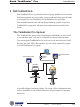
Table Of Contents
- Contents
- About this manual
- 1 Introduction
- The TankRadar Pro System
- Measurement Principle
- 2 Mechanical Installation
- Socket Requirements
- Free Space Requirements
- Dimensions
- Tools
- Mounting the Rod Antenna
- Mounting the Cone Antenna - PTFE sealing
- Mounting the Cone Antenna - Quartz Sealing
- Mounting the Cone Antenna - Process Seal
- Mounting the Parabolic Antenna
- 3 Electrical Installation
- Identication of Installed Options
- Junction Box
- External Connections
- Connecting to a TRL2 Bus Interface
- Connecting HART devices
- Connecting the Display Panel
- Cables
- Safety
- Power Supply
- Grounding
- System Overview
- Internal Connections
- 4 Pro Setup Software
- System Requirements
- Installing the Pro setup software
- Starting the Pro Setup Program
- Setting a Password
- Logging on to a password protected system.
- Setting measurement units
- Installing a Pro Transmitter
- Viewing Level Data
- Service
- 5 Using the Pro Display Panel
- Operation
- Viewing Level Data
- Installing a Pro Transmitter
- Service
- 6 Tank Distances
- Definitions
- Examples
- 7 Technical Information
- Technical Data
- Display Panel
- Analog Outputs
- 8 Troubleshooting
- Display Panel Error Messages

Saab TankRadar
®
Pro
iv
Edition 2. Ref. No: 306010E
Connecting to a TRL2 Bus Interface............................................ 3-6
Connecting HART devices ............................................................ 3-7
Active output (internal loop supply) .............................................. 3-7
Passive output (external loop supply)........................................... 3-7
Intrinsically safe conditions........................................................... 3-8
Non-Intrinsically safe conditions ................................................... 3-8
Connecting the Display Panel ...................................................... 3-9
Cables ........................................................................................... 3-10
Safety ............................................................................................ 3-10
Power Supply ............................................................................... 3-10
Grounding .................................................................................... 3-10
CENELEC .................................................................................. 3-10
FM .............................................................................................. 3-10
System Overview ......................................................................... 3-11
Display Panel ..............................................................................3-11
Analog Outputs............................................................................3-11
Digital Communication.................................................................3-11
Power Supply ..............................................................................3-11
Internal Connections ................................................................... 3-12
Power Supply ............................................................................. 3-12
Display Panel ............................................................................. 3-12
Primary Output ........................................................................... 3-13
Secondary Output ...................................................................... 3-14
4 Pro Setup Software ............................................... 4-1
System Requirements ................................................................... 4-2
Installing the Pro setup software ................................................. 4-2
Starting the Pro Setup Program ................................................... 4-5
Setting a Password........................................................................ 4-6
Logging on to a password protected system. ............................ 4-7