38114 Rosen_cover.
Table of Contents 7 Specifications • Power Supply: DC12V +/- 5% • Power Supply Consumption: 100VAC-240VAC@ 1 Amp • Input: TV/CATV NTSC system, F type connector, Composite NTSC Video/Stereo Audio. • Output: 6.8” TFT Monitor • Stereo speaker output 0.5W(max) Distortion <10%@1KHZ (Volume maximum) 3. Installation of your EM1 • Operating temperature: 0°C~ +40°C 4. Using the Remote Control • Storage temperature: -40°C~ +85°C • Height: 9.25 in. (23.5 cm) • Base Diameter: 6 in. (15.
6 Trouble Shooting Your EM1 3 Installing Your EM1 This section will give a brief trouble shooting guide Please call Rosen Technical Support at 888-883-2790 for further information or technical support. • NO AUDIO - Check volume level. Check MUTE button. Check volume level on AUX. input. Check that correct interface cable is used • NO VIDEO - Check desired source is selected by pressing the MODE button. Check Brightness, Color and Contrast settings.
5 Using Auxiliary Sources 1 EM1 Quick Reference Guide 3 Installing Your EM1 Remote Sensor Lens Your EM1 has the capability to have one auxiliary source plugged into it at a time. This may include DVD players, closed circuit TV, camcorders, video game systems and other NTSC (RCA type) inputs. Plug in your V (video) L (left audio) and R (right audio) RCA cables into the appropriate spot on the EM1 Tuner module.
1 EM1 Quick Reference Guide 4 Using the Remote Control 3 Installing Your EM1 Master Remote Operations User Remote controller The User remote is used for day to day operation. It has basic functions such as: • Volume Up and Down and Mute • Channel Up and Down • Power On and Off • Mode Select Please refer to Section 4, Using the Remote Control, for further details. The intent of the Master remote Master Remote controller is to set up the monitor for client use.
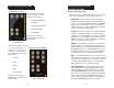
43 Using the Your Remote Installing EM1Control 2 About your EM1 3 Installing Your EM1 Your Rosen EM1 has the following components: Client Remote Operations The client remote has five basic functions. These functions include: • Fully adjustable 6.8” LCD, Infrared remote receiver, with audio speakers. Figure 1 • MODE - This button selects the different types of video sources. The source is indicated in the upper right-hand corner of the monitor when the button is pushed.
3 Installing Your EM1 3 Installing Your EM1 EM-1 FPD A. Getting Started • Locate the desired placement of components to ensure a proper fit. Make sure the monitor has enough room for desired movement. Warning: Excessive moisture and condensation will damage unit. Be sure your chosen location for the interface box and monitor are in a clean dry area. • Ensure there is a wall plug within 4’ of desired Tuner module location before mounting any components. *15 ft.
3 Installing Your EM1 3 Installing Your EM1 B. Mounting of Components (Cont.) • Plug pigtail from monitor into interface cable in J-Box. Table Top or Under Counter Mount • Coil excess (service loop) wire in J-box and mount monitor using supplied screws. • Use the Mounting base plate as a template to mark mounting holes • Replace base cover. • Mount base plate to monitor using 6-32 screws provided • Test for stability and desired range of motion.
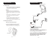
3 Installing Your EM1 3 Installing Your EM1 C. Mounting on Wall to J-Box 2 1 • The EM1 is designed to mount in a round 3 1/2” electrical junction box (J-Box) like the one shown below. J-Box Note : Mounting plate is only used when you want to surface mount your EM1 Interface cable 3 4 Note: A J-box may be purchased at any local hardware store • Make sure J-Box is secure before mounting monitor assembly. • Route 15ft interface cable from j-box to desired Tuner module location.