
Owner's manual


PrintedintheU.S.A.–Rev.05/12 ©2012,ROSS CONTROLS. All Rights Reserved. Form NPS023
WARRANTY and CAUTIONS
Standard ROSS warranty and cautions apply, available upon request or at
www.rosscontrols.com.
ROSS EUROPA GmbH
Germany
Fax: 49-6103-74694
info@rosseuropa.com
ROSS ASIA K.K.
Japan
Fax: 81-427-78-7256
custsvc@rossasia.co.jp
ROSS UK Ltd.
United Kingdom
Fax: 44-121-559-5309
sales@rossuk.co.uk
ROSS SOUTH AMERICA Ltda.
Brazil
Fax: 55-11-4335-3888
vendas@ross-sulamerica.com.br
ROSS CONTROLS INDIA Pvt. Ltd.
India
Fax: 91-44-2625-8730
rossindia@airtelmail.in
DIMAFLUID s.a.s.
France
Fax: 33-01-4945-6530
dimafluid@dimafluid.com
ROSS CONTROLS
(CHINA) Ltd.
China
Fax: 86-21-6915-7960
rosscontrolschina.com
ROSS CONTROLS
U.S.A.
Customer Svs. 1-800-GET-ROSS
Technical Svs. 1-888-TEK-ROSS
www.rosscontrols.com
0
20
30
50
10
40
60
70
90
80
100
0102030405060708090 100
Pressure Drop - PSIG
0
0510 15 20 25 30 35 40 45
Flow - SCFM
Flow - dm /s
Pressure Drop - bar
3
n
1
2
3
4
5
6
Flow Characteristics
RPB12
1/2 Inch Ports
100 PSIG (6.9 bar Primary Pressure
Gauge (Stainless) –160PSIG(0to1100kPa),2"Face RK4520N14160SS
Panel Mount Bracket (Stainless) ............................. R10Y57-SS
Panel Mount Nut – Stainless ............................... R10X51-SS
–Plastic...................................... R10X51-P
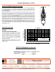
Overview of RPB12 Regulator Operation
Technical Information
Turning the adjusting knob / T-Handle (A) clockwise applies a load to control spring (B) which
forces diaphragm (C) and valve poppet assembly (D) to move downward allowing filtered
air to flow through the seat area (E) created between thepoppet assembly and the seat.
“First stage ltration”.
Air pressure supplied to the inlet port is directed through deflector plate (F) causing a swirling
centrifugal action forcing liquids and coarse particles to the inner bowl wall (G) and down
below the lower baffle (H)tothequietzone.Afterliquidsandlargeparticlesareremovedin
the first stage of filtration “second stage ltration” occurs as air flows through element (J)
where smaller particles are filtered out and retained. The air flow now passes through seat
area (E) to the outlet port of the unit. Pressure in the downstream line is sensed below the
diaphragm (C) and offsets the load of spring (B). When downstream pressure reaches the
set-point, poppet valve assembly (D) and diaphragm (C) move upward closing seat area (E).
Should downstream pressure exceed the desired regulated pressure, the excess pressure will
cause the diaphragm (C) to move upward opening vent hole (K) venting the excess pressure
to atmosphere through the hole in the bonnet (L). (This occurs in the standard relieving type
filter/regulators only.)
CAUTION:
REGULATOR PRESSURE ADJUSTMENT –
The working range of knob adjustment is designed
to permit outlet pressures within their full range.
Pressure adjustment beyond this range is also
possible because the knob is not a limiting device.
This is a common characteristic of most industrial
regulators, and limiting devices may be obtained
only by special design.
For best performance, regulated pressure should
always be set by increasing the pressure up to the
desired setting.
F
G
J
B
L
D
K
A
H
C
E
RPB12 Filter/Regulator Accessories
Technical Specications – RPB12