User’s Manual Diagnostic Software for VW/Audi/SEAT/Skoda 2015 Edition Copyright (c) 2000-2015 by Ross-Tech, LLC. 881 Sumneytown Pike Lansdale, PA 19446 +1-267-638-2300 www.Ross-Tech.
Disclaimer: All rights reserved, No part of this publication may be reproduced, stored in a retrieval system, or transmitted in any form or by any means, electronic, mechanical, photocopying, recording, or otherwise, without the prior written permission of Ross-Tech, LLC. The information contained herein is designed only for use with VCDS diagnostic software. Ross-Tech, LLC. is not responsible for any use of this information as applied to this or other diagnostic equipment. Neither Ross-Tech, LLC.
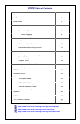
VCDS Table of Contents Subject Getting Started Main Screen Auto-Scan Select Control Module Open Controller Fault Codes Measuring Blocks Data Logging Single Reading Supported Codes Readiness Advanced Identification Advanced Measuring Values Acceleration Measurement Login 7-digit PIN/SKC Dialog Basic Settings Output Tests Recode / Long Coding Adaptation Security Access SRI Reset Generic OBD2 Applications Transport Mode Controller Channels Map EDC-15-16 Mileage Control Module Finder Optical Bus Diagnostics Opt
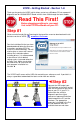
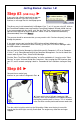
VCDS - Getting Started - Section 1-A Thank you for purchasing VCDS, which allows you to turn a Windows PC into a powerful diagnostic tool for VW/Audi/SEAT/Skoda vehicles from 1990 through the latest models. Read This First! Before plugging anything in, you must first install VCDS software on your PC. Step #1 Go to our website and click on Download at the top of the screen to download and install the latest version of VCDS: www.Ross-Tech.
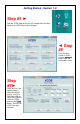
Getting Started - Section 1-B Step #3 (USB Only) ► If you are using a Serial Interface then you can proceed to step #4. If you are using a USB Interface, a message like this should pop up: ► The drivers may install automatically in Windows Vista, 7, or 8. If you are using XP, click on the Found New Hardware message and the Found New Hardware Wizard should start up. If you are prompted with the choice, pick “No, Not This Time” when asked if you want to connect to the Internet to search for drivers.
Getting Started - Section 1-C Step #5 ► Start the VCDS program on your PC through either the Start Menu or the VCDS icon on your Desktop. ◄ Step #6 From the Main Screen in VCDS click the [Options] button to go into the Options screen. Step #7► Once you are in the Options Screen, Select the correct port for your PC’s USB Port (USB) or Serial Port (typically COM1 or COM2) and click the [Test] button. Ensure that VCDS finds your interface.
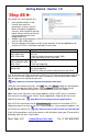
Getting Started - Section 1-D Step #8 ► You should see a message like this: If the Interface Status is “Not Found!” then check the connections at the car and PC. Make sure both are plugged in securely. Serial Interfaces get their power from the vehicle so they will not be recognized at all if not plugged into a car. Adapter Type should always be “Ross-Tech” followed by the name of the Interface such as “HEX-USB+CAN”. Version indicates the firmware version of your Interface.
VCDS - Main Screen - Section 2-A This screen appears when you start VCDS by clicking the shortcut on your Desktop or by selecting VCDS from the Start Menu. These screen-shots were taken using Microsoft Windows 7 with the "Aero" style. If you are not using 7 Aero, expect the screens to look different but the functions will be the same.
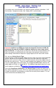
VCDS – Auto Scan - Section 3-A (VAG 1551/1552 function 00) This function scans each controller in the vehicle to retrieve controller information - VAG Part Numbers, Component number, Soft. Coding, WSC, and fault codes. Important! AutoScan is probably the single most important function in VCDS. We recommend that you run and SAVE a complete AutoScan on every single vehicle that you work on.
Auto Scan cont. - Section 3-B There is a file in the VCDS directory called MyAutoScan.txt, where you can create a custom profile for your vehicle. It can be edited by simply clicking on the hyperlink above the Chassis Type selection. This will open the file in your default Text editor (like Notepad) to create a custom profile for your vehicle. To help you figure out which controllers are in your car, you can run the Control Module Finder in section 28 of this manual.
Auto-Scan cont. - Section 3-C [Gateway Installation List] Only available on Gateways in cars using a direct CAN connection for diagnostics, this function is also accessible from the Applications Screen. This very fast function takes about 3 seconds to query the car's Gateway to find out what modules are installed in the car and what their status is. Any modules having fault codes should show a "Malfunction" and will be highlighted in RED.
Auto-Scan cont. - Section 3-D The VIN should be retrieved automatically from all cars which "know" their VIN. Also in control modules that provide it, engine codes and Jxxx component identifiers are shown as well. Results: If you close the Auto-Scan dialog, any data in its output box will be lost. If you would like to keep a record, click the [Copy] button first, then you can paste the results into the application of your choice, such as MS Word or Notepad.
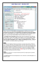
VCDS- Select Control Module- Section 4-A The various computers in the car are called “Control Modules” or “Controllers”. On this screen, you select which Control Module you want to "talk" to. To establish communications with a particular Control Module, simply click on the appropriate button. For example, click on the [01 – Engine] button to connect to the engine controller. Module Tabs: Each tab on the top of this screen contains a number of different controllers grouped by category.
VCDS - Open Controller- Section 5-A This screen will appear when VCDS is establishing communications with any of the Control Modules shown on the Select Control Module screen. Comm Status Shows the status of the current communications session. Once communications have been established: IC= Shows the number of times the session has been initialized. If IC increases beyond 1, communications are less than 100% reliable. TE= is a counter of transmitter errors within individual packets.
Open Controller cont. - Section 5-B Controller Info Once the communications session has been established, all of the Control Module’s "Identification" data is presented here. VAG Number is the VW/Audi part number for this controller. All of the digits, both numbers and letters, make up the part number. In some cases this number may be different from the number on the sticker on the module itself, specifically if the module has been reflashed by a dealer per a service campaign.
VCDS - Fault Codes - Section 6-A (VAG 1551/1552 functions 02 and 05) On this screen, VCDS shows you any DTCs (“Diagnostic Trouble Codes” or Fault Codes) present in the control module in which a communications session is currently active. VCDS shows the DTC numbers and also decodes each DTC into meaningful text. At the top of the screen is shown the VAG Number and Component number as found on the Open Controller screen. VCDS tells you how many fault codes have been found and displays each of them.
Fault Codes cont. - Section 6-B The Display Freeze Frame Data checkbox adds Freeze Frame data for Fault Codes on control modules using the KWP-2000 / CAN / UDS protocols. Keep in mind that many control modules are not aware of the actual date and time, so they may display bogus dates, just as they do with the factory scan tools. Note: Not all control modules fully support this.
Fault Codes cont. - Section 6-C [Print Codes] will print a Fault Code Report. If your PC is not connected to a printer when this button is pressed, be sure to use Windows to set the printer to "Work Off-Line" first! Later, when you connect the PC to a printer, un-check "Work Off-Line" to print the report. [Copy Codes] will copy your fault codes to Windows Clipboard. Once you have pressed the Copy Codes button, you may paste the results into the application of your choice, such as MS Word or Notepad.
VCDS - Measuring Blocks - Section 7-A (VAG 1551/1552 function 08) On this screen, you can read all sorts of data from the Control Module in real-time. Use [Up] and [Dn] to scroll through the available groups (000 - 255 on most Control Modules) and you can view up to three groups at the same time. Don't become discouraged when you find some that say "ERROR: Group xxx Not Available" or if you find some groups where the fields are all blank.
Measuring Blocks cont. - Section 7-B You can [Log] the data from the measuring blocks. For more information see Data Logging (Section 8 of this manual). [Switch to Basic Settings] can be used to go to Basic Settings for the Group that is currently being displayed. This should be done only under guidance from the Service Manual or when following some other documented procedure. For more information, see the Basic Settings function (Section 17 of this manual).
Measuring Blocks cont. - Section 7-C Label Files also allow a third label field to be defined for each of the normal measuring block fields. This label is displayed in a balloon when the user hovers over the field. The idea is to put "specified values" in this field: Sample Rate: Some ECUs may not be willing to produce more than about 3.5 samples per second when running a single group, even with the most aggressive protocoltiming settings. Other ECUs may be much faster.
Measuring Blocks cont. - Section 7-D If you'd like to record just a snapshot in time of the current readings in each group, click on [Add to Log]. This will save the results to your PC, typically in your VCDS\Logs directory Acceleration Measurement When you have one or more measuring group with speed (km/h) in it, clicking on [Acceleration] will bring up the Acceleration Measurement window, which allows you to enter start and stop speeds and distances.
VCDS - Data Logging - Section 8-A You can log the data from the Measuring Blocks screen to a comma-separated *.CSV file. These files can be opened and analyzed with Excel or other spreadsheet applications or played back using VC-Scope (see Section 32 of this manual). Export RPM only when checked will record only RPM from the first field and will not record other fields. Also, this will only record RPM values that are non-zero.
Data Logging cont. - Section 8-B Dual ECU's: For vehicles with dual ECU's (like the Audi R8), data from both ECU's can be logged simultaneously by accessing [31 – Engine Other] as shown here: The [Marker] button places a sequential number in the file when you click it. This can be helpful for data analysis. The [Browse] button allows you to specify the location for your logs.
Data Logging cont. - Section 8-C Example using Microsoft Excel: 1. Choose the group or groups that you want to view. 2. Click the [Log] button 3. Use default file name if desired. It will append the old file if you use a particular name more than once. 4. Click [Start] 5. Drive the car through the tests that you want to perform 6. Click [Stop] 7. Click [Done, Close] when you're finished logging data. 8. Open Microsoft Excel 9. Click File->Open (change filetype to all *.*) 10. Locate the *.
VCDS - Single Reading- Section 9-A (VAG 1551/1552 function 09) This function allows you to look at real-time data from control modules that support it. However, the data stream coming from the control module gives NO CLUE what the data means or how to scale it into real-world values. The only way to know what the values mean is to find a reference to this function in the Factory Repair Manual for your car. This function is rare, but it is used, for example, with some OBD-I 2.8L 12V V6 engines.
VCDS – Supported Codes- Section 10-A Supported Codes function: Only some KWP2000/CAN/UDS control modules support this function and there is no way to tell which have this capability without trying the function. VCDS can show all DTC and Failure Mode combinations which a control module is capable of detecting, including the current status of each. You can sort the results by selecting the radio buttons on the right side of the screen. Use [OK] to return to the Controller Info / Select Function screen.
VCDS - View Readiness - Section 11-A (VAG 1551/1552 function 15) The Readiness Code is a set of 8 bits, each of which corresponds to one monitored emissions "system" in an OBD-II car. When all readiness bits show "Passed", it means that all systems have been checked and have passed the on-board tests. Whenever you clear DTCs, all readiness bits that are testable will be set to "Fail" or "Failed or Incomplete".
View Readiness cont. - Section 11-B VCDS also decodes Readiness bits into meaningful data on modern TDI engines including US-market Common-Rail TDI-140 engines. Diesel Readiness is a VCDS exclusive, not even the VAS-5051/5052 does this: Click on [Save] to store the results to your PC, typically in this directory on your PC: C:\Ross-Tech\VCDS\Logs Use [Go Back] to return to the Open Controller screen.
View Readiness cont. - Section 11-C The Guided Readiness Scripts function will guide the user through the process of setting Readiness on those engines which support it by clicking on the [Set Readiness] button. The button will be grayed out if Readiness bits are already set (you can clear fault codes to un-set them) or if appropriate documentation does not exist in VCDS for that specific ECU: Guided Readiness Scripts require supporting data in Label files.
VCDS - Advanced Identification - Section 12-A (VAS 5051/5052 “Identification Services”) Corresponds to VAS-5051/5051 "Identification Services" This function displays additional (and sometimes quite arcane) identifying data from the control module which does not fit on the Open Controller screen. Notes: The Advanced ID function is not available on control modules using the old KW1281 protocol. The amount of data appearing on this screen will vary based on what the control module supports.
VCDS - Advanced Measuring Values - Section 13-A This function expands on the Measuring Blocks function and lets you select up to 12 measuring values from as many as 12 different groups from a selection dialog that shows the contents of the measuring values. This function is available only when a label file exists for the control module being accessed. For controllers using the UDS/ODX/ASAM protocol, the Measuring Blocks function is not available and you MUST use Advanced Measuring Blocks instead.
Advanced Measuring Values cont. - Section 13-B VCDS lets you save a list of Advanced Measuring Values, to be easily accessed later on. For instance, if you often log Vehicle Speed, Engine Speed, Intake Air Mass, and Ignition timing, then you can create a file to quickly load those selections again. To save a set of items, click on the VCDS logo found on the top left corner of the item selection window, and then select "Save selection to file": Give the file a name and specify the directory if desired.
VCDS – Acceleration Measurement - Section 14-A When you have one or more Measuring Blocks or Advanced Measuring Values with speed (km/h) in it, clicking on [Acceleration] will bring up the Acceleration Measurement window, which allows you to enter start and stop speeds and distances. After entering the values you want to measure, click [Start]. Next, do your acceleration runs in a safe and legal location. The "clock" will start counting when the car starts to accelerate.
VCDS - Login - Section 15-A (VAG 1551/1552 function 11) The Login Function must be used on some (but not all) Control Modules before you can Recode or change Adaptation values. On others, it "enables" certain features like cruise control. Valid Login codes can be found in the Factory Repair Manual for your car. If you are working on an Immobilizer, select [Use 7-digit PIN/SKC] to enter a 7-digit Secret Key Code. This function is described in Section 16.
VCDS - 7-digit PIN/SKC - Section 16-A The 7-digit PIN/SKC (Secret Key Code) dialog is used for Key Matching and Immobilizer Adaptation. This function is still in VCDS but is pretty much obsolete since VW/Audi stopped giving out 7-digit SKC's in 2005. Just in case you obtained your 7-digit SKC before then (along with the necessary WSC, Importer and date the code was generated), instructions on using this function can be found on our website: http://ross-tech.com/vcds-lite/manual/pinskc.
VCDS - Basic Settings - Section 17-A (VAG 1551/1552 function 04) Basic Settings mode is very similar to Measuring Blocks and the contents of each display group is the same. The difference between the functions is that the Control Module may try to perform various calibrations while in Basic Settings mode. The most common use for the Basic Settings function is to recalibrate the Throttle Body. Another common use for Basic Settings is to bleed the ABS Hydraulic Unit on some cars.
Basic Settings cont. - Section 17-B You can begin and end a Data [Log] while in Basic Settings. See section 8 of this manual for information on Data Logging. For control modules that have a Label File with Basic Settings information, a drop-down menu is available which allows you to select from the supported Basic Settings functions. Below that menu is an area to display additional info for Basic Settings.
Basic Settings cont. - Section 17-C On UDS control modules that offer "Instructions", VCDS will automatically display them.
Basic Settings cont. - Section 17-D Notes: Multiple Groups are not permitted in Basic Settings. The data presented in each Basic Settings Group varies greatly from Control Module to Control Module and between different models and years. Some groups are documented in the Factory Repair Manuals, but many are not. VCDS tries to elaborate on the meaning of the data as much as possible but the "Data Type" information coming from the Control Module is not very precise.
VCDS - Output Tests - Section 18-A (VAG 1551/1552 function 03) The Output Tests function is used to test a Control Module's Electrical Outputs (and the wiring that connects it to the various devices). Output Tests under KWP-2000/CAN/UDS includes simultaneous measuring data when available from the control module in question, in UDS by clicking on the [Measuring Values] button. To begin sequential Output Tests, and to progress through each step, click [Start/Next].
Output Tests cont. - Section 18-B On most systems, the Output Tests function is only available when the Engine is not running. It is perfectly normal to see a "short to ground" message in the process of running Output Tests. The ECU identifies which output it is currently testing by sending a fault-code number. On many ECUs the full text for this fault code includes "short to ground".
Output Tests cont. - Section 18-C Selective Output Tests. On those modules that support it, this is a more sophisticated version of the traditional (sequential) Output Test function. It allows the user to select a particular output and activate it directly without going through a pre-defined sequence to get there. Some modules have outputs which can only be tested this way. Selective Output Tests requires supporting data in a label file (or ROD file for UDS modules).
Output Tests cont. - Section 18-D Measuring Values can be displayed during Output Tests in UDS/ODX modules. This can be handy to verify that certain outputs are functioning as intended by clicking on the [Measuring Values] button: Use [Done, Go Back] to return to the Open Controller screen.
VCDS - Recode or Long Coding - Section 19-A (VAG 1551/1552 function 07) Recode is used to set various options in a Control Module. Note: Some Modules require a valid Login before you can re-code them. Warning! You should refer to the Factory Repair Manual for your particular car (or some other documented procedure) before attempting to Recode a Control Module. At the very least, write down the original values, saving an AutoScan is a great way to do that.
Recode cont. - Section 19-B A feature unique to VCDS: You can leave the WorkShop Code unchanged, or enter any workshop code you desire. Certain other programs always leave a tell-tale WSC when you re-code a module. The Importer Number is only relevant for recoding controllers that use KWP-2000. By default, this will remain unchanged unless you have set up an Importer Number in the Options screen.
Recode cont. - Section 19-C As long as the Index entered is valid and documentation exists in the appropriate label file, the new Coding (either short coding or Long Coding) should be entered into the Software Coding field: See the Airbag Coding Page on our Website for more info: www.Ross-Tech.com/vag-com/cars/airbag-coding.html Coding of Slave Modules. On the latest cars, many "slave" modules are codeable.
Recode cont. - Section 19-D Long Coding. This function is needed to Code some control modules in cars that use CAN for diagnostics. Due to the complexity of Long Coding strings (up to 255 bytes of hexadecimal data) we've accommodated (and urge) the use of Copy & Paste in this function and usage of the Long Coding Helper. Check the Soft reset box (UDS only) if it is mentioned in repair instructions. Long Coding Helper is used with applications such as Niels Ezerman's excellent LCode.
Recode cont. - Section 19-E Some coding configurations require multiple bits to be changed.
Recode cont. - Section 19-F On some newer vehicles like the 8T0 (Audi B8 platform), the Gateway Installation is not accessible via Long Coding. In such cases, use the [Installation List button in the Open Controller screen for 19 - CAN Gateway to access this screen. This function is available in all Gateways that support an Installation list: If an uninitialized control module warning appears, this means that one or more of the WorkShop Code, Importer, or Equipment numbers are all zeros.
VCDS – Adaptation / Long Adaptation - Section 20-A (VAG 1551/1552 function 10) The Adaptation function allows you to alter certain values and/or settings in control modules that support it. Warning! You should refer to the Factory Repair Manual for your particular car (or some other documented procedure) before "playing" with the Adaptation function.
Adaptation / Long Adaptation cont. - Section 20-B Label Files can support values and descriptions for Adaptation channels. A help chart may be displayed in a balloon. For control modules that have a Label File with Adaptation information (or for UDS modules with a ROD file), a drop-down menu will be shown, which allows you to select from the supported functions: Once you have reached a channel of interest, you can use the [Up] and [Dn] buttons next to New Value to incrementally change the value.
Adaptation / Long Adaptation cont. - Section 20-C UDS: For controllers using the UDS/ODX/ASAM protocol, the drop-down menu MUST be used, since traditional Adaptation Channels do not apply. VCDS supports Adaptation for all control modules in the VW Crafter / LT3 as explained on this page on our website: http://ross-tech.com/vcds/tour/LT3.
VCDS - Security Access Screen - Section 21-A (VAG 1551/2 Function 16, KWP-2000 only) The Security Access Function must be used on some (but not all) KWP-2000/CAN/UDS Control Modules before you can Recode or change Adaptation values. On others, it "enables" certain features like cruise control. Valid Security Access codes can be found in the Factory Repair Manual for your car.
VCDS – SRI Reset- Section 22-A The [SRI Reset] function is used to reset the Service Reminder in vehicles so equipped. The function will automatically access the Instrument Cluster and will retrieve SRI instructions from the Label File as well as current values stored in the Cluster. New values can be entered by hand, or the user can select the drop-down list to choose from a number of functions which will load standard value sets.
SRI Reset cont. - Section 22-B The [Save to logfile] button can be useful when there are questions about or difficulties with the SRI function as it's an easy way to send us a snapshot of what's going on. Data is saved to the Session Log , typically in your C:\Ross-Tech\VCDS\Logs directory. Upon clicking [Perform SRI] the new values will be stored in the (often less than intuitive) sequence required. After cycling the ignition, the cluster should no longer indicate that service is due.
VCDS – Generic OBD2 - Section 23-A (VAG 1551/1552 Address Word 33) Generic OBD-II functionality. Because many of VW's recent factory repair manuals no longer have traditional 01-Engine "On Board Diagnostic" information and have replaced it with "Generic Scan Tool" data, this has become much more important than it was in the past. Click each of the Mode buttons to access each OBD-II function. Generic OBD-II functionality is "Supported" only on VW, Audi, Seat, and Skoda cars.
Generic OBD2 cont. - Section 23-B Interfaces: Our HEX+CAN and HEX-NET interfaces support ISO 9141-2 ("CARB"), ISO 14230 ("KWP-2000") and ISO-15765 ("CAN") protocols. Our non-CAN HEX-, KEY-, and KII- series interfaces support ISO 9141-2 ("CARB"), ISO 14230 ("KWP-2000"), but do not support ISO-15765 ("CAN"). Our Micro-CAN interface supports ISO-15765 ("CAN"), but do not support ISO 9141-2 ("CARB") or ISO 14230 ("KWP-2000") for generic OBD-II.
VCDS - Applications- Section 24-A The Applications screen contains many handy functions, most of which are described in individual sections on the following pages. Check for and erase faults [Gateway Installation List] Only available only on Gateways in cars using a direct CAN connection for diagnostics. This very fast function takes about 3 seconds to query the car's Gateway to find out what modules are installed in the car and what their status is.
VCDS – Transport Mode - Section 25-A Transport Mode On some vehicles using CAN for diagnostics, there is a special Transport Mode that is used by the factory to put the cars into a "sleep" mode to conserve battery charge during long periods of inactivity. [Activate Transport Mode] Clicking this button (when using a HEX interface) will put applicable vehicles into Transport Mode, shutting down most systems.
VCDS – Controller Channels Map - Section 26-A [Controller Channels Map] Rapidly scans through all 255 possible Measuring Block groups or Adaptation Channels on any controller and writes a "map" file. Choose the Controller Address (such as 01 for Engine), then any Login or security access code (not needed in most cases, contact Ross-Tech for assistance), then select either Measuring Blocks or Adaptations or both. Output is your choice of .CSV or .PLB / .
VCDS – EDC-15-16 Mileage Checker - Section 27-A [EDC-15-16 Mileage] is found in the Applications Screen and is used to show an independent "odometer" reading stored in the ECU. EDC-15 is found in older TDI engines like the North American market VE 1.9L Golf/Jetta/etc. EDC-16 is used in 2.0L TDI's including all North American PD engines, but not in the newest CR engines. This function also works with some EDC-15 V6 TDI ECUs.
VCDS - Control Module Finder - Section 28-A This function found in the Applications Screen cycles through each possible address in the vehicle, finding each controller and reporting its Address number, Name, Protocol, Part Number, Component Number, Coding, and WorkShop Code. Note: No one car has all Modules! Newer cars have more, older cars have fewer. You can scan selected address ranges or use the default starting and ending addresses.
VCDS – Optical Bus Diagnostics - Section 29-A The [Optical Bus Diagnostics] function found in the Applications Screen is used on models with a MOST bus to narrow down the location of a break in the network. Many control modules will be completely inaccessible via conventional diagnostics if there's a break in the MOST bus. The above example shows a 4F Audi A6 with a break in the MOST bus.
VCDS – Options Screen – Section 30-A On this screen you can set a number of Options organized by tabbed sections that must be used the first time you run VCDS on a PC.
Options Screen cont. – Section 30-B Port and Protocol Options tab: Select Port Select the radio button for the COM Port to which you have connected the Interface. Serial Ports should be assigned to COM1 through COM4 (most often COM1 by default) while USB has only its eponymous choice. The NET setting is used by the HEX-NET interface when it is operating in WiFi mode, see this page for more infornation: http://www.ross-tech.
Options Screen cont. – Section 30-C Protocol Options cont. Blk Int affects the protocol timing. The current default value is 55. To get the highest sample rate possible in the Measuring Blocks screen, set this to 25. Note, however, that this may cause unreliable communications with some controllers. Char lnt also affects the protocol timing. The current default value is 1. To get the highest sample rate possible in the Measuring Blocks screen, set this to 0.
Options Screen cont. – Section 30-D [Restore Defaults] will reset all Protocol Options (except WorkShop Code and VZ/Importer number) to their "as-delivered" settings. If you right-click on the VCDS icon on the top left of the VCDS Main Screen, you can select “Delete config file and close”. This can be very handy, especially if you have made the window size too large.
Options Screen cont. – Section 30-E User Interface and Identification cont. Disable Sounds Unchecked by default, checking this box will prevent VCDS from making sounds when an operation is complete, for example at the end of an AutoScan or at the end of Acceleration Measurements. This will not prevent Windows sounds when an error message pops up.
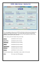
VCDS - About Screen – Section 31-A License Info The Serial Number will initially be “Please test on car to see serial number” until you have connected to a car and checked fault codes in a controller. After you have done this, you will have a Serial Number composed of letters, numbers and hyphens. License Status should always be Valid / Activated, with all of our Current Interfaces since they store their own activation.
VC-Scope Graphing ‘Plug-In’ for VCDS- Section 32-A VC-Scope is automatically installed when you install VCDS. Quick Instructions: You can use VC-Scope in one of two ways: o View live data while connected to a car by launching VAG-Scope. Click the [Graph] button on VCDS's Measuring Blocks screen, o View data previously logged with VCDS by manually starting VCScope in stand-alone and opening a VCDS Log file You cannot do both at the same time.
VC-Scope cont. - Section 32-B Quick Instructions cont: Click on a field to select it for vertical scaling. Then change the Max and Min values in the Vertical scale boxes. Click back on a field showing data to see changes. VC-Scope will remember all scaling values for a particular control module by part number.
TDI Timing Checker ’Plug-In’ for VCDS - Section 33-A The TDI Timing Checker is automatically installed when you install VCDS. Note: This ONLY applies to VE Engines and DOES NOT apply to PD (unit injectors) or CR (common rail) engines This plug-in allows you to check the injection timing setting on a VE TDI engine (NOT PD or CR varieties). This needs to be done after you change the timing belt and should be done every once in a while to keep tabs on belt stretch and pump/pulley alignment.
TDI Timing Checker cont. - Section 33-B Step by step: Start your engine and make sure the coolant is up to normal running temp Start VCDS Click [Select] Click [01-Engine] Click [Meas. Blocks-08] Go to group 000 Click [Switch to basic settings] Click [TDI Timing] It is normal for the glowplug light to flash and for the engine sound to change slightly while using this function. This thread may be helpful as well: http://forums.tdiclub.com/showthread.
VCDS - What’s New - Section 34-A Main Screen: New number of Codes loaded AutoScan: MyAutoScan.TXT is used to customize vehicle/controller list. Added OS and VM identification to results. Fault Codes: Updated CODES.DAT file now with almost 21,000 codes. Fixed incorrect Freeze-Frame in 2011+ Touareg EPB. Advanced Measuring Values: New data entry box for filtering items.
VCDS 2015 Version User Manual Copyright © 2015 by Ross-Tech, LLC rev 06/30/15