
User manual


Software Upgrade Procedure
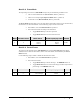
U13
Socket
Model
Version
Label Area
Board Issue
Label Area
U34
Socket
Corner
Bevel
Corner
Bevel
JP7
Firmware
Upgrade
Jumper
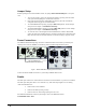
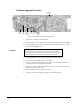
Figure 8. Frame Synchronizer Socket and Label Location
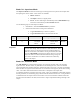
1. Remove the card from the mounting frame.
2. Refer to Figure 8 and the card labeling to locate the existing IC chip in socket U13.
3. Insert the supplied IC chip removal tool, with the toothed-end inward, in one of the
corner slots of the U13 socket.
Important
Do not press the tool too far into the slot or you may catch against
the mounting socket’s frame, where it connects to the card itself.
Excessive prying may damage the socket frame or the card or both.
Follow the instructions included with the chip extraction tool.
4. Alternating between corners, gently pry up the chip from the socket.
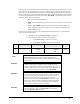
5. Store the old chip in a labeled static free container.
6. Carefully remove the new chip from the packaging. The chip and the socket each
have one beveled corner for alignment purposes.
7. Align the new chip over the socket with the beveled corners together and the label
facing up. Text direction may vary.
8. Gently and firmly press the chip into the socket.
9. Proceed to the Firmware Upgrade Procedure on the following page.
6-4 • Frame Synchronizer Upgrade ADC-8032B User Manual (Iss. 02B)