ADC-9532 Analog Audio to AES/EBU Converter User Manual
ADC-9532 User Manual • Ross Part Number: 9532DR-004-02 • Release Date: October 11, 2012. The information contained in this manual is subject to change without notice or obligation. Copyright © 2012 Ross Video Limited. All rights reserved. This work is proprietary and confidential to Ross Video Limited, its subsidiaries and its other affiliated corporations and may not be copied, distributed, sold or otherwise used or relied upon without the express written permission of Ross Video Limited.
Important Regulatory and Safety Notices to Service Personnel Before using this product and any associated equipment, refer to the “Important Safety Instructions” listed below to avoid personnel injury and to prevent product damage. Product may require specific equipment, and/or installation procedures to be carried out to satisfy certain regulatory compliance requirements. Notices have been included in this publication to call attention to these specific requirements.
Important Safety Instructions 1. Warning – Read these instructions. 2. Keep these instructions. 3. Heed all warnings. 4. Follow all instructions. 5. The safe operation of this product requires that a protective earth connection be provided. A grounding conductor in the equipment's supply cord provides this protective earth. To reduce the risk of electrical shock to the operator and service personnel, this ground conductor must be connected to an earthed ground. 6.
EMC Notices United States of America FCC Part 15 This equipment has been tested and found to comply with the limits for a class A Digital device, pursuant to part 15 of the FCC Rules. These limits are designed to provide reasonable protection against harmful interference when the equipment is operated in a commercial environment.
“Contact Us” section on the last page of this manual. All GearLite products are covered by a generous 3-year warranty and will be repaired without charge for materials or labor within this period. See the “Warranty and Repair Policy” section in this manual for details. Environmental Information The equipment that you purchased required the extraction and use of natural resources for its production. It may contain hazardous substances that could impact health and the environment.
Introduction Overview The ADC-9532 is a broadcast quality Analog Audio to AES/EBU Converter used to convert two (2) analog audio channels to an AES/EBU signal. The ADC-9532 accepts one stereo (A, B) analog audio pair and provides three (3) copies of the AES/EBU signal. The conversion from analog to digital is performed with 20bit or 24bit precision. The ADC-9532 supports sampling rates of 32kHz and 48kHz (with a video or AES reference or free running) and 44.1kHz (with a valid AES reference signal only).
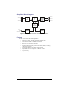
Simplified Block Diagram ANLG IN A AMPLIFIER & FILTER ANLG IN B 24BIT A/D AES TRANSMITTER & OUTPUT DRIVERS AES OUT 1 AES OUT 2 AES OUT 3 CONTROL LOGIC & PROCESSING AES OR ANLG VIDEO REFERENCE AES/VIDEO REFERENCE PROCESSING USER SETTINGS & STATUS Figure 1 Simplified Block Diagram of ADC-9532 Functions Features The ADC-9532 includes the following features: • • • • • • • Support for 32kHz, 44.
Installation Static Discharge Whenever handling the ADC-9532 and other related equipment, please observe all static discharge precautions as described in the following note: ESD Susceptibility — Static discharge can cause serious damage to sensitive semiconductor devices. Avoid handling circuit boards in high static environments, such as carpeted areas, and when wearing synthetic fiber clothing. Always exercise proper grounding precautions when working on circuit boards and related equipment.
removed for adjustments. Carefully consider the installation location before proceeding; the adhesive is very aggressive and is not easily removed. The adhesive will cure fully in 24 hours. To install the Surface Mount Strips 1. Remove the Protective Backing Film from the adhesive on the bottom of the two VELCRO® brand Surface Mount Strips. 2. Adhere the Surface Mount Strips to the bottom side of the chassis. (Figure 2) Figure 2 Surface Mount Installation Option 3.
Flat Metal Plate Use the flat metal plate for permanent mounting to a rack, a desk, or any other location where bolts or screws can be applied. Be sure to position the module to allow for operator adjustments, if required. To install the Flat Metal Plate 1. Remove the 2 screws from the bottom of the chassis. 2. Install the Flat Metal Plate onto the bottom of the chassis (Figure 3) using the screws provided in the Mounting Kit. Do not use the screws removed during Step 1.
Figure 4 Angle Mounting Bracket 11 • Installation (Iss.
Setup Power Adapter and Supply Connect the PS-9000 power adaptor to the power supply connector. The PS-9000 provides up to 2A of regulated +5V DC (5%). The DC power cord has a locking connector that securely fastens into the power supply DC jack on the ADC-9532. The ADC-9532 has a standard miniature power jack (center pin positive).
AES Connections Connect the digital outputs as required from the three AES BNC connectors. It is not necessary to terminate unused outputs. Analog Connections On the rear edge of the ADC-9532 there is a removable 12-pin audio terminal block which has slots for the positive, negative, and grounded wires of two balanced analog audio cables. To wire the cables to the connector 1. Gently pull the block from the unit. 2.
Table 1 DIP Switch Positions Switch Number Down Position Up Position 1 Ch. A Headroom Adjust +24dBu Ch. A Headroom Adjust +20dBu 2 Ch. B Headroom Adjust +24dBu Ch. B Headroom Adjust +20dBu 3 AES Reference Video Reference 4 Emphasis Off Emphasis On 5 24Bit 20Bit 6 Other Rate 32kHz 7 Other Rate 44.1kHz 8 Other Rate 48kHz SW1 - Channel A Headroom Use this switch to choose between 24dB or 20dB levels for AES Channel A.
SW6 - 32kHz Sampling Rate Set this switch UP to select the 32kHz sampling rate. Use with an AES or video reference as required. Ensure SW7 and SW8 are set to DOWN. SW7 - 44.1kHz Sampling Rate Set this switch UP to select the 44.1kHz sampling rate. Use with an AES reference only. Ensure SW6 and SW8 are DOWN. The ADC-9532 will only provide a 44.1kHz sampled signal as long as it has a valid 44.1kHz AES reference signal. On loss of the 44.
LED POWER Color Table 2 Status LED Descriptions Function Green When lit, this LED indicates the ADC-9532 is powered on. Off When unlit, this LED indicates a loss of power. a.The ADC-9532 will track the AES reference signal if the rate selection is incorrect. Potentiometer Setup The ADC-9532 can accommodate any full-scale digital (FSD) level in the -17dBFS to -27dBFS range. The analog stereo input signal from the 12-pin terminal block consists of an A and B channel (left and right).
Audio Levels A M P L I T U D E Saturation A M P L I T U D E 0dBFS Saturation Headroom Operating Level +4dBu or +8dBu Operating Level -20dBu or -24dBu DISTORTION DISTORTION Figure 9 Analog Audio Figure 10 Digital Audio Figure 9 illustrates amplitude vs. distortion for analog and digital audio equipment show that digital audio does not gradually degrade (become more distorted) as the amplitude increases. Likewise, the digital audio signal does not exist above 0dBFS.
Specifications Technical Specifications Specifications are subject to change without notification. Table 5 ADC-9532 — Technical Specifications Category Parameter Specification Number of Inputs Analog Audio Connector Input Impedance Reference Input 2 balanced channels (1 stereo pair) via removable terminal strip 12-pin screw-type >25kohm CMRR >70dB (20Hz to 20kHz) Max. Input Level Range +17 to +27dBu (limit is variable) Inputs AES-3id or analog video (NTSC/PAL) Sampling Rates 32kHz, 44.
Table 5 ADC-9532 — Technical Specifications Category Parameter Specification AES/EBU Output Performance Power Other Output Isolation 45dB Output Return Loss >45dB (0.1 to 6MHz) DC Offset <50mV Quantization 20bit or 24bit Frequency Response ±0.10dB @ 48kHz (20Hz to 20kHz) Signal to Noise Ratio Measured at -20dBFS -102dB unweighted -105dB ‘A’ weighted -112dB CCITT weighted THD+N Measured at -20dBFS -102dB (<0.006%) Linearity 0.002dB to -120dBFS Phase Linearity 0.
Channel Status Data Table indicates fixed and configurable channel status bit information. Table 6 Channel Status Data Byte Bit Function Transmitted 0 Professional or Consumer use of Channel Status Block Professional (1) 1 Normal Audio or Non-audio mode Normal Audio (0) 2-4 Emphasis: user selectable • Not indicated or No emphasis (000) • 50/15us Emphasis (110) 0 5 6-7 Source Sampling Rate Locked (0) Sampling Rate: user selectable Set according to current sampling rate: • 32kHz (11) • 44.
Service Information Warranty and Repair Policy The GearLite ADC-9532 is warranted to be free of any defect with respect to performance, quality, reliability, and workmanship for a period of THREE (3) years from the date of delivery to the customer. In the event that your GearLite ADC-9532 proves to be defective in any way during this warranty period, Ross Video Limited reserves the right to repair or replace this piece of equipment with a unit of equal or superior performance characteristics.
Notes: Service Information (Iss.
Contact Us Contact our friendly and professional support representatives for the following: • Name and address of your local dealer • Product information and pricing • Technical support • Upcoming trade show information Technical Support Telephone: +1 613 • 652 • 4886 After Hours Emergency: +1 613 • 349 • 0006 Email: techsupport@rossvideo.com Telephone: +1 613 • 652 • 4886 General Information Fax: +1 613 • 652 • 4425 Email: solutions@rossvideo.com Website: http://www.rossvideo.