Ross Video Limited ASI-310 ASI-to-SMPTE 310 and SMPTE 310-to-ASI Converters User Manual
ASI-310 • ASI-to-SMPTE 310 and SMPTE 310-to-ASI Converters User Manual • Ross Part Number: ASI310DR-004-03 • Release Date: January 18, 2012. The information contained in this manual is subject to change without notice or obligation. Copyright © 2012 Ross Video Limited. All rights reserved. Contents of this publication may not be reproduced in any form without the written permission of Ross Video Limited. Reproduction or reverse engineering of copyrighted software is prohibited.
Important Regulatory and Safety Notices Before using this product and any associated equipment, refer to the “Important Safety Instructions” listed below to avoid personnel injury and to prevent product damage. Products may require specific equipment, and/or installation procedures to be carried out to satisfy certain regulatory compliance requirements. Notices have been included in this publication to call attention to these specific requirements.
EMC Notices United States of America FCC Part 15 This equipment has been tested and found to comply with the limits for a class A Digital device, pursuant to part 15 of the FCC Rules. These limits are designed to provide reasonable protection against harmful interference when the equipment is operated in a commercial environment.
Environmental Information The equipment that you purchased required the extraction and use of natural resources for its production. It may contain hazardous substances that could impact health and the environment. To avoid the potential release of those substances into the environment and to diminish the need for the extraction of natural resources, Ross Video encourages you to use the appropriate take-back systems.
Company Address Ross Video Limited Ross Video Incorporated 8 John Street Iroquois, Ontario Canada, K0E 1K0 P.O. Box 880 Ogdensburg, New York USA 13669-0880 General Business Office: (+1) 613 • 652 • 4886 Fax: (+1) 613 • 652 • 4425 Technical Support: (+1) 613 • 652 • 4886 After Hours Emergency: (+1) 613 • 349 • 0006 E-mail (Technical Support): techsupport@rossvideo.com E-mail (General Information): solutions@rossvideo.com Website: http://www.rossvideo.
Contents Introduction 1 Overview.............................................................................................................................. 1-2 Features.................................................................................................................. 1-2 Functional Block Diagram................................................................................................... 1-3 User Interfaces ...........................................................................
Using the On-Screen Menus 5 On-screen Display Overview ............................................................................................... 5-2 OSD Switch Overview .......................................................................................... 5-2 OSD Layout and Navigation ................................................................................................ 5-3 Using the Menus .................................................................................................
Introduction In This Chapter This chapter contains the following sections: • Overview • Functional Block Diagram • User Interfaces • Documentation Terms and Conventions A Word of Thanks Congratulations on choosing an openGear ASI-310 ASI to SMPTE 310 and SMPTE 310 to ASI Converters. Your ASI-310 is part of a full line of Digital Products within the openGear Terminal Equipment family of products, backed by Ross Video’s experience in engineering and design expertise since 1974.
Overview The ASI-310 accepts a DVB-ASI input containing an MPEG 2 Transport Stream, and produces a SMPTE 310M Transport Stream output at one of two standard frequencies: 19.392659 or 38.785317 Mbps. It also simultaneously accepts a 310M Transport Stream at either of the standard frequencies and produces a DVB-ASI signal. The ASI-310 provides a number of innovative tools to simplify your workflow.
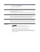
Functional Block Diagram This section provides a functional block diagram that outlines the workflow of the ASI-310. 310 OUT ASI IN EQUALIZE/ DESERIALIZE CONVERT ASI-310 RE-STAMP PCR SERIALIZE 310 MON OUT CPU GPI/Os TC/VCXO PLL OSD 310 IN CONVERT 310-ASI MUX SERIALIZE ASI/OSD OUT Figure 1.1 Simplified Block Diagram — ASI-310 ASI-310 User Manual (Iss.
User Interfaces The ASI-310 includes three user interfaces. DashBoard Control System™ The DashBoard Control System™ enables you to monitor and control openGear frames and cards from a computer. DashBoard communicates with other cards in the DFR-8300 series frame through the Network Controller Card. The DashBoard Control System software and manual are available for download from our website. For More Information... • on the ASI-310 menus in DashBoard, refer to the chapter “Configuration” on page 4-1.
Documentation Terms and Conventions The following terms and conventions are used throughout this manual: • All references to the DFR-8300 series frame also includes all version of the 10-slot (DFR-8310 series) frames, 20-slot (DFR-8322 series) frame, and any available options unless otherwise noted. • “525-line mode” refers to broadcast situations using NTSC composite (analog) signal reference inputs.
1–6 • Introduction ASI-310 User Manual (Iss.
Installation In This Chapter This chapter provides instructions for installing the ASI-310, installing the card into the DFR-8300 series frame, cabling details, and updating the card software. The following topics are discussed: • Before You Begin • Quick Start • Installing the ASI-310 • Cabling for the ASI-310 • Software Upgrades ASI-310 User Manual (Iss.
Before You Begin Before proceeding with the instructions in this chapter, ensure that your DFR-8300 series frame is properly installed according to the instructions in the DFR-8300 Series User Manual. Static Discharge Throughout this chapter, please heed the following cautionary note: ESD Susceptibility — Static discharge can cause serious damage to sensitive semiconductor devices. Avoid handling circuit boards in high static environments such as carpeted areas and when synthetic fiber clothing is worn.
Quick Start Assuming you have an openGear frame, an ASI-310 card and a suitable rear module, the following steps will get you started with ASI-to-310 conversion: 1. Connect the frame to your LAN. Refer to the DFR-8300 Series User Manual and the MFC-8300 Series User Manual for details. 2. Install DashBoard on a computer connected to the LAN. The DashBoard Control System™ software and user manual is also available for download from the Ross Video website. 3.
Installing the ASI-310 This section outlines how to install a rear module and card in a DFR-8300 series frame. Refer to the section “Cabling for the ASI-310” on page 2-6 for cabling details. Rear Modules When installing the ASI-310: • DFR-8310 series frames — The MDL-R10 Full Rear Module is required. The ASI-310 is not compatible with the DFR-8310-BNC frames. • DFR-8321 series frames — The MDL-R20 Full Rear Module is required.
Installing the ASI-310 Use the following procedure to install the ASI-310 in a DFR-8300 series frame: 1. Locate the Rear Module you installed in the procedure “Installing a Rear Module” on page 2-4. Notice — Heat and power distribution requirements within a frame may dictate specific slot placements of cards. Cards with many heat-producing components should be arranged to avoid areas of excess heat build-up, particularly in frames using convectional cooling. 2.
Cabling for the ASI-310 This section provides information for connecting cables to the installed rear modules on the DFR-8300 series frames. It is not necessary to terminate unused outputs. Rear Module Cabling This section provides cabling diagrams for the rear modules. The type of rear module depends on the frame the card is installed in. DFR-8310 Series Frames Each MDL-R10 Full Rear Module accommodates one card and uses two slots.
ASI In — BNC 4 or BNC 5 BNC 4 (BNC 5 on the MDL-R10) accepts an ASI Transport Stream input for conversion to SMPTE 310M. The input signal is internally terminated in 75ohms when the ASI-310 is installed and unterminated otherwise. 310 Out — BNC 3 BNC 3 carries the SMPTE 310M output produced by conversion of the ASI input. When the ASI-310 is removed from its slot, the rear module bypasses BNC 1 to BNC 3 directly. 310 Monitor — BNC 2 BNC 2 carries an inverted copy of the 310 output.
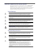
Refer to Figure 2.4 for pinouts on the MDL-R10 and Figure 2.5 for pinouts on the MDL-R20. G 8 7 6 5 4 3 2 1 Figure 2.4 GPI/O Pinouts for the MDL-R10 2–8 • Installation 1 2 3 4 5 6 7 8 G Figure 2.5 GPI Pinouts for the MDL-R20 ASI-310 User Manual (Iss.
Software Upgrades This section provides instructions for upgrading the software for your ASI-310 using the DashBoard Control System™. Use the following procedure to upgrade the software on a ASI-310: 1. Contact Ross Technical Support for the latest software version file. 2. Launch the DashBoard client on your computer. 3. Display a tab for the card you wish to upgrade by double-clicking its status indicator in the Basic Tree View. 4.
2–10 • Installation ASI-310 User Manual (Iss.
User Controls In This Chapter This chapter provides a general overview of the user controls available on the ASI-310. The following topics are discussed: • Card Overview • Control and Monitoring ASI-310 User Manual (Iss.
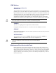
Card Overview This section provides a general overview of the ASI-310 card-edge components. 1 2 3 Figure 3.1 ASI-310 — Card-edge Components 1) OSD Switch (SW1) 2) Menu Switch (SW2) 3) Reset Button (SW3) 1. OSD Switch (SW1) This slide switch can be used to enable the analog and SDI on-screen displays. • IN — When the switch is set to the IN position (closer to the rear of the card), the ASI/OSD output is from the 310-to-ASI converter.
Control and Monitoring This section summarizes the LEDs on the ASI-310 card-edge. Refer to Figure 3.2 for the location of the LEDs. POWER LED (DS1) OSD LED (DS2) OSD Switch (SW1) DS3 LED DS4 LED ASI IN LED (DS5) ASI/OSD OUT LED (DS6) Menu Switch (SW2) UNKNOWN REAR MODULE LED (DS7) VIDEO ERROR LED (DS8) OSD LED (DS9) ASI IN LED (DS10) 310 IN LED (DS11) ASI OVERFLOW LED (DS12) Reset Button (SW3) Figure 3.
Table 3.1 LEDs on the ASI-310 LED ASI IN (DS5) ASI/OSD OUT (DS6) Color Display and Description Green When lit green, this LED indicates the ASI input is present and valid. Red When red or flashing red, this LED indicates that no valid input is present. This typically means that the input cable is disconnected. Green When lit green, this LED indicates that the ASI/OSD output serializer has a valid input. Red When lit red, this LED indicates a hardware fault on the card.
Configuration In This Chapter This chapter explains how to use the user interface to set up the ASI-310. This discussion is based on the use of DashBoard through a network connection. The order of sections in this chapter follows the workflow required to setup the ASI-310 for operation. It is recommended that you proceed through the following sections in order to achieve the best possible understanding of the product.
On-screen Display Settings If you are using the on-screen display feature of the ASI-310, you must configure the display options in the Settings tab in DashBoard. To configure the on-screen display settings: 1. Launch the DashBoard client on your computer. 2. Display a tab in the Device View for the card you wish to configure by double-clicking its status indicator in the Basic Tree View. 3. From the Device View, select the Settings tab. 4. Set the OSD Background Color to suit your requirements.
ASI-to-310 Converter Settings The ASI to 310 tab provides options for configuring the ASI-to-310 converter feature. To set up the ASI-to-310 converter: 1. Select the ASI to 310 tab. ASI to 310 Tab 2. Use the 310 Output Bit Rate options to set the output data rate. 3. Use the Output Packet Size options to specify the number of bytes per packet in the 310 output. This is normally 188 bytes, but you can set it to 204 or 208 bytes if needed for your application.
310-to-ASI Converter Settings There are two modes for the 310-to-ASI converter: • Packet Mode — All the bytes of each TS packet are output consecutively, and fill characters (K28.5) are inserted between packets. When there are no bytes ready for transmission, K28.5 characters are transmitted. • Byte Mode — Each SMPTE 310 byte that arrives at the converter input is transmitted on the ASI output as soon as it is ready.
GPI/O Settings Use the following procedure to assign GPI/O outputs to error conditions: 1. Select the GPIO tab. 2. Select the GPI/O that you want to assign from the selector labeled GPI/O. The eight selections are named GPIO 1 through GPIO 8. If you have renamed the GPI/Os (discussed in the section “String Settings” on page 4-6), the names you have assigned will display in this list instead. 3. Use the provided buttons to select the Condition that you want to trigger it.
String Settings The Edit Strings tab allows you to assign a name to this ASI-310 card, to distinguish it in DashBoard from other cards of the same type. It also lets you assign descriptive names to the GPI/O outputs. To configure a string: 1. Select the Edit Strings tab. Edit Strings Tab 2. Enter a unique name in the Card ID field.
Alarm Settings The Alarms Settings tab allows you to specify the conditions that are included in the Card Status tab and reported though SNMP if enabled on the frame. To specify the error conditions to report: 1. Select the Alarms Settings tab. Alarms Settings Tab 2. Select the Unsupported Rear Module box to report when the ASI-310 does not work properly with the installed rear module; for example, it may be missing connectors that are essential for the ASI-310's operation. 3.
Monitoring This section provides an explanation of the status tabs available when using DashBoard to monitor the ASI-310. For a more complete description of DashBoard and its capabilities, refer to the DashBoard User Manual. Product Tab The Product tab displays read-only information that is useful in discussing the operation of the card with Ross Video’s Technical Support staff.
GPIO Status Tab The GPIO Status tab displays the following read-only information: • The Card Status, Incoming ASI, Incoming SMPTE 310, and Outgoing 310 Null Rate fields report the same information as described in the Alarm Status tab. • The GPIO 1-8 fields indicate the state of the eight GPI/O outputs. The normal non-error state of these GPI/Os is typically “low”; in this case, any that display “high” indicate a currently existing error condition that you need to investigate.
4–10 • Configuration ASI-310 User Manual (Iss.
Using the On-Screen Menus In This Chapter This chapter explains how to use the Menu switch (SW2) functions available on the On-screen Display (OSD) of the ASI-310. It does not describe each available menu; for information on these, refer to the chapter “Configuration” on page 4-1. The purpose of this chapter is to explain how to navigate the menus and access the available functions and settings.
On-screen Display Overview This section briefly describes how to access and navigate through the menus in the on-screen display (OSD). The OSD feature is displayed on a separate composite monitoring output. When activated, the card status and parameters can be viewed and adjusted using the card-mounted menu switch and an easy to use menu system. For More Information... • on the switch locations on the card-edge, refer to the section “Card Overview” on page 3-2.
OSD Layout and Navigation When the ASI-310’s front OSD switch is in the normal “in” position, the OSD is off and its output jack is the output from the 310-to-ASI converter. To use the OSD, move it to the “out” position (closer to the front-edge of the card). A menu, similar to the one shown below, is displayed on the OSD output. ASI-310 Convertor Product Settings Product Manufacturer Hardware Rev Software Rev Firmware Rev Rear Module Current (mA) Serial Number OSD Enabled EXIT ASI-310 B A A.
Using the Menus The available menus that can be selected via the OSD are described in Table 5.1. Table 5.1 Available Menus Status (left column) Setup Menus (center column) Exit (right) Product Settings Exit GPIO Status ASI to 310 Alarms 310 to ASI Alarm Counters GPIO Edit Strings Alarms The use of the menus to change settings will be illustrated by the following example: 1.
Specifications In This Chapter This chapter provides the technical specification information for the ASI-310. Note that technical specifications are subject to change without notice. The following topics are discussed: • Technical Specifications ASI-310 User Manual (Iss.
Technical Specifications This section provides technical specifications for the ASI-310. . Table 6.
Service Information In This Chapter This chapter contains the following sections: • Troubleshooting Checklist • Warranty and Repair Policy ASI-310 User Manual (Iss.
Troubleshooting Checklist Routine maintenance to this openGear product is not required. In the event of problems with your ASI-310, the following basic troubleshooting checklist may help identify the source of the problem. If the frame still does not appear to be working properly after checking all possible causes, please contact your openGear products distributor, or the Technical Support department at the numbers listed under the “Contact Us” section. 1.
Warranty and Repair Policy The ASI-310 is warranted to be free of any defect with respect to performance, quality, reliability, and workmanship for a period of FIVE (5) years from the date of shipment from our factory. In the event that your ASI-310 proves to be defective in any way during this warranty period, Ross Video Limited reserves the right to repair or replace this piece of equipment with a unit of equal or superior performance characteristics.
Contact Us Contact our friendly and professional support representatives for the following: • Name and address of your local dealer • Product information and pricing • Technical support • Upcoming trade show information PHONE General Business Office and Technical Support 613 • 652 • 4886 After Hours Emergency 613 • 349 • 0006 Fax 613 • 652 • 4425 General Information solutions@rossvideo.com Technical Support techsupport@rossvideo.