
User manual


2–6 • Installation ASI-310 User Manual (Iss. 03)
Cabling for the ASI-310
This section provides information for connecting cables to the installed rear modules on the
DFR-8300 series frames. It is not necessary to terminate unused outputs.
Rear Module Cabling
This section provides cabling diagrams for the rear modules. The type of rear module depends on
the frame the card is installed in.
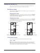
DFR-8310 Series Frames
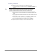
Each MDL-R10 Full Rear Module accommodates one card and uses two slots. Each MDL-R10
provides a SMPTE 310M input, an ASI input, a SMPTE 310M monitoring output, one SMPTE
310M output, and an ASI output. (Figure 2.2)
DFR-8321 Series Frames
Each MDL-R20 Full Rear Module accommodates one card and uses two slots. Each MDL-R20
provides a SMPTE 310M input, an ASI input, a SMPTE 310M monitoring output, one SMPTE
310M output, and an ASI output. (Figure 2.3)
Connections Overview
This section briefly outlines the types of connections available on the rear modules.
310 In — BNC 1
BNC 1 accepts a SMPTE 310M Transport Stream input which can be converted to ASI and/or
used as a frequency reference for the 310 output. The input signal is internally terminated in
75ohms when the ASI-310 is installed. When the ASI-310 is removed from the rear module, this
input is terminated in the equipment connected to the 310 Out BNC.
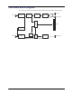
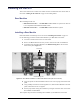
Figure 2.2 Cabling for the MDL-R10 Rear Module Figure 2.3 Cabling for the MDL-R20 Rear Module
5
6
310 In
ASI In
ASI/OSD Out
3
310 Out
GPIOs
1
310 MON
Out
2
4
ANLG OSD
Out
310 In
ASI In
310 MON Out
ASI/OSD Out
310 Out
GPIOs
4
5
3
1
2