DRA-8604 Dual 3G/HD/SD Reclocking Amplifier User Manual
DRA-8604 User Manual • Ross Part Number: 8604DR-004-02 • Release Date: July 25, 2013. The information in this manual is subject to change without notice or obligation. Copyright © 2013 Ross Video Limited. All rights reserved. This work is proprietary and confidential to Ross Video Limited, its subsidiaries and its other affiliated corporations and may not be copied, distributed, sold or otherwise used or relied upon without the express written permission of Ross Video Limited.
Important Regulatory and Safety Notices to Service Personnel Before using this product and nay associated equipment, refer to the “Important Safety Instructions” listed below to avoid personnel injury and to prevent product damage. Product may require specific equipment, and/or installation procedures to be carried out to satisfy certain regulatory compliance requirements. Notices have been included in this publication to call attention to these specific requirements.
EMC Notices United States of America FCC Part 15 This equipment has been tested and found to comply with the limits for a class A Digital device, pursuant to part 15 of the FCC Rules. These limits are designed to provide reasonable protection against harmful interference when the equipment is operated in a commercial environment.
Environmental Information The equipment that you purchased required the extraction and use of natural resources for its production. It may contain hazardous substances that could impact health and the environment. To avoid the potential release of those substances into the environment and to diminish the need for the extraction of natural resources, Ross Video encourages you to use the appropriate take-back systems.
Company Address Ross Video Limited Ross Video Incorporated 8 John Street P.O. Box 880 Iroquois, Ontario, K0E 1K0 Ogdensburg, New York Canada USA 13669-0880 General Business Office: (+1) 613 • 652 • 4886 Fax: (+1) 613 • 652 • 4425 Technical Support: (+1) 613 • 652 • 4886 After Hours Emergency: (+1) 613 • 349 • 0006 E-mail (Technical Support): techsupport@rossvideo.com E-mail (General Information): solutions@rossvideo.com Website: http://www.rossvideo.
Contents Introduction 1 Overview.............................................................................................................................. 1-2 Features.................................................................................................................. 1-2 Functional Block Diagrams ................................................................................................. 1-3 Dual 1x8 Configuration.....................................................................
Specifications 5 Technical Specifications ...................................................................................................... 5-2 Service Information 6 Troubleshooting Checklist ................................................................................................... 6-2 Bootload Button..................................................................................................... 6-2 Warranty and Repair Policy ..........................................................
Introduction In This Chapter This chapter contains the following sections: • Overview • Functional Block Diagrams • User Interfaces • Documentation Terms and Conventions A Word of Thanks Congratulations on choosing an openGear DRA-8604 Dual 3G/HD/SD Reclocking Amplifier. Your DRA-8604 is part of a full line of products within the openGear Terminal Equipment family of products, backed by Ross Video’s experience in engineering and design expertise since 1974.
Overview Your DRA-8604 is a 3G Multi-Definition SDI distribution amplifier, capable of equalizing and reclocking all common serial digital signals. Each channel of your DRA-8604 equalizes the incoming SDI signal, compensating for greater than 400m of cable at 270MHz, greater than 150m of cable at 1.485GHz, and greater than 100m of cable at 2.97GHz. An LED indicator at the front of the card identifies the presence of incoming video simplifying system troubleshooting.
Functional Block Diagrams The DRA-8604 can operate as a reclocking dual 1x8 or as a dual 1x4. The configuration depends on the rear module you are using. This section provides the block diagrams for all configurations. Dual 1x8 Configuration Figure 1.1 describes the workflow of the DRA-8604 with the 8320AR-302 Full Rear module. This configuration has the DRA-8604 operating as a dual reclocking 1x8 with HD-BNC connections.
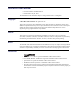
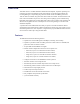
Single 1x16 Configuration Figure 1.3 describes the workflow of the DRA-8604 with the 8320AR-302 Full Rear module and the Channel Option menu set to Single Channel (1x16). This configuration has the DRA-8604 operating as a single reclocking 1x16 with HD-BNC connections. OUT 1 OUT 2 OUT 3 IN CH A OUT 4 Equalizer Reclocker OUT 5 OUT 6 OUT 7 OUT 8 OUT 9 OUT 10 OUT 11 OUT 12 BACKUP IN Equalizer Reclocker OUT 13 OUT 14 OUT 15 OUT 16 Figure 1.
User Interfaces The following interfaces are available for control and monitoring of your DRA-8604. DashBoard Control System™ The DashBoard Control System™ enables you to monitor and control openGear frames and cards from a computer. DashBoard communicates with other cards in the openGear frame through the Network Controller Card. For More Information on... • menus in DashBoard, refer to the section “DashBoard Menus” on page 4-1. • installing and using DashBoard, refer to the DashBoard User Manual.
Documentation Terms and Conventions The following terms and conventions are used throughout this manual. Terms The following terms are used: • “Board” and “Card” both refer to the card, including all components and switches. • “DashBoard” refers to the DashBoard Control System™. • “DFR-8321 series” refers to the DFR-8321 series frames and all available options unless otherwise indicated. • “Network Controller Card” refers to the MFC Series Network Controller Cards unless otherwise indicated.
Installation In This Chapter This chapter provides instructions for installing the rear module for your DRA-8604, installing the card in the openGear frame, cabling details, and how to upgrade the software on your card(s). The following topics are discussed: • Before You Begin • Installing the DRA-8604 • Cabling • Software Upgrades DRA-8604 User Manual (Iss.
Before You Begin Before proceeding with the instructions in this chapter, ensure that your openGear frame is properly installed according to the instructions in the DFR-8300 and OG3-FR Series User Manual. Static Discharge Throughout this chapter, please heed the following cautionary note: ESD Susceptibility — Static discharge can cause serious damage to sensitive semiconductor devices.
Installing the DRA-8604 The procedure for installing the rear module and card in your openGear frame is the same regardless of the rear module used. The DRA-8604 can be installed in the DFR-8321 series frames and the OG3-FR series frames using one of the supported rear modules. Supported Rear Modules Notice — Ensure that you install the DRA-8604 using one of the supported rear modules listed below. Installing the DRA-8604 with an unsupported rear module can damage the card, the rear module, or both.
5. Align the top hole of the rear module with the screw hole on the top edge of the frame back plane. 6. Using a Phillips screwdriver and the supplied screw, fasten the rear module to the back plane. Do not over-tighten. 7. Verify whether your Rear Module Label is self-adhesive by checking the back of the label for a thin wax sheet. You must remove the wax sheet before affixing the label. 8. Affix the supplied Rear Module Label to the BNC area of the Rear Module. 9.
Cabling The DRA-8604 can operate as a dual 1x8, or a dual 1x4 depending on the rear module you are using. This section provides cabling details based on the configuration. Important — It is necessary to terminate unused outputs. Dual 1x8 Configuration The 8320AR-302 Full Rear Module is required when operating in a dual 1x8 configuration. Each rear module occupies two slots and accommodates one card. This rear module provides one SDI input and eight SDI outputs per channel on HD-BNC jacks. (Figure 2.
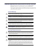
Single 1x16 Configuration The 8320AR-302 Full Rear Module is required when operating in a single 1x16 configuration. Each rear module occupies two slots and accommodates one card. This rear module provides one SDI input, one backup input, and sixteen SDI outputs on HD-BNC jacks. (Figure 2.4) Card 1 SDI IN OUT 1 OUT 3 OUT 5 OUT 7 OUT 9 OUT 11 OUT 13 OUT 15 Card 2 1 2 3 4 5 6 7 8 9 10 11 12 13 14 15 16 17 18 BACKUP IN OUT 2 OUT 4 OUT 6 OUT 8 OUT 10 OUT 12 OUT 14 OUT 16 Figure 2.
Software Upgrades The DRA-8604 can be upgraded in the field via the Network Controller Card in your openGear frame. Note that DashBoard version 5.1.0 or higher is required for this procedure. To upgrade the software on a card 1. Contact Ross Technical Support for the latest software version file. 2. Display the Device View of the card by double-clicking its status indicator in the Basic Tree View. 3. From the Device View, click Upload to display the Select file for upload dialog. 4. Navigate to the *.
2–8 • Installation DRA-8604 User Manual (Iss.
Configuration In This Chapter This chapter provides a general overview of the user controls available on your DRA-8604. The following topics are discussed: • Card Overview • Monitoring Features • Using DashBoard • Configuring the DRA-8604 DRA-8604 User Manual (Iss.
Card Overview This section describes the Bootload button located on each card surface. There are no other card-edge controls as all configuration and setup is done using the menus in DashBoard. Refer to Figure 3.1 for location of this button. Figure 3.1 Card-edge Controls 1. Bootload Button This button is used for factory service in the unlikely event of a complete card failure. Do not use this button unless advised by Ross Technical Support. For More Information on...
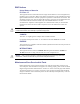
Monitoring Features The following sections describe the card-edge LEDs. Refer to Figure 3.2 for LED locations. PWR LED INPUT A LED INPUT B LED Bootload Button Figure 3.2 LED Locations Status LEDs Basic LED displays and descriptions are provided in Table 3.1. Table 3.1 Status LEDs LED PWR Color Green When lit green, this LED indicates that the card is functioning normal and that no anomalies have been detected.
Using DashBoard Before proceeding, ensure that the DashBoard Control System™ is installed on a PC connected to your facility network. The DashBoard software and user manual are available from the Ross Video website. For More Information on... • installing DashBoard, refer to the DashBoard User Manual. To launch DashBoard 1. Ensure that you are running DashBoard software version 5.1.0 or higher. 2. Launch DashBoard by double-clicking its icon on your desktop. 3.
Configuring the DRA-8604 This section briefly outlines how to configure the DRA-8604 using the options available in DashBoard. Enabling a Single Channel Configuration You can configure the card to operate in a single channel configuration via the Channel Options menu in the Setup tab. The options in the menu vary depending on the full rear module that you are using. The channels are automatically re-named as Channel A-1 and Channel A-2 on the Setup and Signal tabs.
• Channel A-2 — IN 1 is the primary input source and IN 2 is the backup source. To enable the failover feature 1. From the Device View, select the Setup tab. 2. Select the Enable Failover check box for the channel. The box displays a check-mark. Configuring the Equalizer for a Channel This section summarizes how to set up the equalizer for a channel. To enable the equalizer 1. From the Device View, select the Setup tab. 2. Select the Enable Equalizer check box for the channel.
To enable an alarm for a loss of input 1. From the Device View, select the Alarms tab. 2. Select the Alarm on Loss of Input check box for the channel. The box displays a check-mark. The Status fields in the Signal tab now report when the card detects an invalid or absent input signal for that channel. To verify which BNC to troubleshoot, refer to the rear module labelling or the Input BNC status field in the Setup tab. DRA-8604 User Manual (Iss.
3–8 • Configuration DRA-8604 User Manual (Iss.
DashBoard Menus In This Chapter This chapter briefly summarizes the menus, items, and parameters available from DashBoard for your card. Default parameters are noted with an asterisk (*). The following topics are discussed: • Status Tabs • Setup Tab • Alarms Tab DRA-8604 User Manual (Iss.
Status Tabs This section summarizes the read-only information displayed in the Status tabs. The fields in the Signal tab vary in severity from green (valid), yellow (caution), to red (alarm). DashBoard reports the most severe alarm for a single field. Alarm colors are noted within the tables as text set in brackets next to the menu parameter name. Signal Tab Table 4.1 outlines the read-only information displayed in the Signal tab. Table 4.
Table 4.
Product Tab Table 4.3 outlines the read-only information displayed in the Product tab. Table 4.3 Product Tab Items Tab Title Item Parameters Description Product DRA-8604 Displays the card model Supplier Ross Video Ltd. Indicates the manufacturer of your card Board Rev ## Indicates the version of the PCB Board S/N ###### Indicates the card serial number # Indicates the rear module the card is installed in Unknown Indicates that the installed rear module is not recognized by the card ##.
Setup Tab Table 4.4 summarizes the Setup options available in8320AR-302 DashBoard. Table 4.
Alarms Tab Table 4.5 summarizes the Alarms options available in DashBoard. Table 4.5 Alarm Enables Menu Items Menu Title Channel #a Item Parameters Description Selected* The Status fields in the Signal tab reports the loss of the specified input as an error/alarm Cleared The Status fields in the Signal tab reports the loss of the specified input as information only Alarm on Loss of Input a. If the fields are labeled as Channel A-1 and Channel A-2, the Channel Options menu is set to Single Channel.
Specifications In This Chapter This chapter includes the technical specifications for the DRA-8604. Note that specifications are subject to change without notice. The following topics are discussed: • Technical Specifications DRA-8604 User Manual (Iss.
Technical Specifications This section lists the technical specifications for the DRA-8604. Table 5.1 Technical Specifications Category Rear Modules Parameter Specification Supported Rear Modules 8320AR-300, 8320AR-302 Number of Inputs 2 270Mbps, 525/625 Component, SMPTE 259M Data Rates and SMPTE Standards Accommodated 270Mbps, SMPTE 310 270Mbps, DVB-ASI 1.485Gbps Component, SMPTE 292M 2.
Service Information In This Chapter This chapter contains the following sections: • Troubleshooting Checklist • Warranty and Repair Policy DRA-8604 User Manual (Iss.
Troubleshooting Checklist Routine maintenance to this openGear product is not required. In the event of problems with your card, the following basic troubleshooting checklist may help identify the source of the problem. If the frame still does not appear to be working properly after checking all possible causes, please contact your openGear products distributor, or the Technical Support department at the numbers listed under the “Contact Us” section at the end of the manual. 1.
Warranty and Repair Policy The DRA-8604 is warranted to be free of any defect with respect to performance, quality, reliability, and workmanship for a period of FIVE (5) years from the date of shipment from our factory. In the event that your DRA-8604 proves to be defective in any way during this warranty period, Ross Video Limited reserves the right to repair or replace this piece of equipment with a unit of equal or superior performance characteristics.
Notes:
Notes:
Contact Us Contact our friendly and professional support representatives for the following: • Name and address of your local dealer • Product information and pricing • Technical support • Upcoming trade show information Technical Support Telephone: +1 613 • 652 • 4886 After Hours Emergency: +1 613 • 349 • 0006 Email: techsupport@rossvideo.com Telephone: +1 613 • 652 • 4886 General Information Fax: +1 613 • 652 • 4425 Email: solutions@rossvideo.com Website: http://www.rossvideo.