
Operator`s manual

1–2 • Introduction CrossOver 6 / 12 User Manual (v4.0)
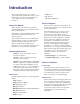
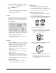
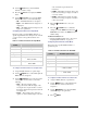
Figure 1.1 Installing the Frame in an Equipment Rack
To install the rear support brackets to your frame:
1. The rear support bars can be attached to the
frame in one of the possible positions illustrated
in Figure 1.1. Choose the position that suits the
cabinet depth that will give approximately 1/2
inch projection beyond the rear vertical
mounting rails.
2. Using four screws per bar, fasten one bar to each
side of the frame.
3. Mount the frame to the front rails of the rack
cabinet using four rack screws fastened through
the front mounting flanges.
4. At the rear of the cabinet, slide the bracket slots
over the rear of the support bars and secure to
the cabinet rear rails with two rack screws each.
Cabling
Refer to the Getting Started Guide for instructions
on connecting all cables to your switcher control
panel and frame.
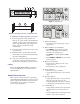
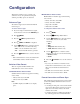
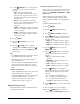
Control Panel Overview
The CrossOver 12 and CrossOver 6 control panels
offer similar functionality. The CrossOver 12 control
panel is equipped with additional source buttons, key
control buttons, and a positioner for additional
control of wipes and patterns.
Figure 1.2 CrossOver 12
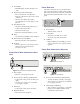
Figure 1.3 CrossOver 6
1. Pattern Select Buttons
• Press buttons in the pattern group to select
wipe patterns.
2. Menu and Memory Control Buttons
• Press MENU to access the menu system.
Press one of the Pattern Select buttons to
select the corresponding menu.
• Press NEXT to cycle through the available
menus.
• Press STORE and RECALL to save and load
memory registers.
3. Menu Screen and Knobs
• Rotate a knob to change the menu option
displayed above it.
• Press the knob to select a menu item.
4. Key Type Buttons
• Selects the key type for all keys.
• Assigns Key/Aux bus to Key 1 (CrossOver 6
only).
5. Key Select Buttons
• Assigns the Key/Aux bus to a keyer when the
button is pressed (CrossOver 12 only).
• Assigns the Key/Aux bus to Key 2 or Aux bus
1 when button is pressed (CrossOver 6 only).
6. Aux Bus Buttons
• Assigns the Key/Aux bus to the selected Aux
bus when button is pressed (CrossOver 12
only).
• Aux bus assignment is done through the menu
interface on CrossOver 6 switchers.
1
2
3 4
1/2"
3
2
1
4 5
6
7
8
9
10
11
12
3
2
1
4 5
7
8
9
10
11