
Operator`s manual


CrossOver 6 / 12 User Manual (v4.0) Advanced Operation • 4–11
Resetting Menu Items
The values for particular parameters can be reset
individually. This allows you to restore the default
setting if you are unsatisfied with the adjusted
values.
Some parameters are shared between features and, if
reset in one area, will be reset in all areas that share
that parameter.
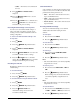
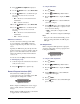
To reset individual menu items:
1. Select the menu for the value you wish to reset.
2. Double press the knob associated with the value.
Restoring the Default Bus Map
You can restore your switcher to the default Bus Map
if you no longer wish to use a customized Bus Map.
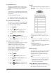
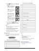
To restore the default Bus Map:
1. Press MENU.
2. Press the RESET Wipe Pattern button.
3. Press NEXT until Dfault BusMap
appears.
4. Press the Dfault BusMap knob.
5. Press the Confrm knob to perform the reset.
Press the Cancel knob to cancel the reset.
Restoring to Factory Defaults
You can restore your switcher to the factory default
settings. You may wish to do this when
troubleshooting problems with your switcher.
Restoring to factory defaults resets the entire
switcher. Save any configuration information to a
memory register if you wish to re-load it after
performing the factory default.
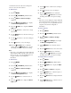
To restore factory defaults:
1. Press MENU.
2. Press the RESET Wipe Pattern button.
3. Press NEXT until Factry Reset appears.
4. Press the Factry Reset knob.
5. Press the Confrm knob to perform the reset.
Press the Cancel knob to cancel the reset.
Tallies
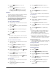
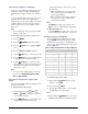
The switcher has tally relays assigned to inputs as
follows (pin 1 is the top right pin when looking at the
Tally Port):
Figure 4.2 Tally Port
When the corresponding input is on-air, the
associated tally pin is closed, creating a contact
closure.
Note:
• Tally wiring can be difficult. Consult with your
facility engineer before undertaking any tally
wiring.
For More Information on...
• port locations, refer to the section “Frame Rear
Connections Overview” on page 1-3.
Device Control
Your switcher can connect to and control a variety of
external broadcast equipment. Refer to the Ross
Video External Device Setup Sheet for your
particular device for complete connection and
configuration information.
Note:
• Device control menus are easily accessed even
when the switcher auto-follows to a different
menu. Refer to the section “Auto-Follow” on
page 1-4 for more information.
Adding, Modifying, and Removing Devices
External devices must be added to the switcher and
then assigned to an input before they can be
MENU
NEXT
MENU
NEXT
Table 4.4 Tally Port Pinout
Pin Input
11
23
35
47
5 Common Ground
62
74
8
6
9
8
54321
9876