
Installation guide

Every auto transition rate is constantly visible - including the main transition rates, the
dedicated keyer rates, and the fade to black rate. The last memory number recalled is also
displayed along with an associated eight-character memory name.
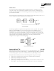
General Purpose Interface
The Synergy 1 is equipped with twelve dedicated GPI inputs and twelve dedicated GPI
outputs. The GPI inputs allow the switcher to interface with peripheral equipment such as
editors and DVEs. Each GPI input can be used to perform simple editing and switcher
functions such as fade to black or an auto transition on the switcher’s MLE. For more
complex editing capabilities with the switcher, option S1-060: Editor Interface is available.
GPIs can also be used by DVEs to indicate Aux Bus on air status to the switcher. For more
complex DVE integration, refer to option S1-062: DVE Send and Remote Control. GPI
outputs are used to trigger remote events like “Still Store Next Page” and can be tied to the
switcher’s Custom Control buttons.
Control Panel Tallies
The standard system includes 16 tally relays in the control panel of the Synergy 1. Tally
connections are located on the rear of the Synergy 1 control panel. These connections
provide a contact closure and are fully assignable - any tally can be assigned to any video
input.
System Manuals
The Synergy 1 comes with a complete set of system documentation that includes an
Operation Guide, an Installation Guide, and a Maintenance Guide.
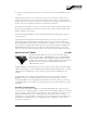
10 Meter Control Cable
The Synergy 1 control panel and rack frame are connected by a single, standard 8-pin flat-
shielded Telco cable that uses RS-422 communication. The maximum cable length
between the control panel and its rack frame is 1,000 feet or 305 meters.
Page 11 of 36 March, 2005 Synergy 1 SD Ordering Guide, v16