
User's Manual
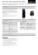

Table Of Contents

AY-L23 G/H and SA-23 G/H
Outdoor Long-Range RF Reader and Remote Control May 2013
Installation and Operation Manual
1
1. Introduction
The AYL-23G/H is an outdoor long-range RF reader that acts as a
receiver. It is compatible with Rosslare’s SA-23 wireless remote control
transmitter. The AY-L23 G works with the SA-23 G (433.92 MHz) and
the AY-L23 H works with the SA-23 H (868.35 MHz).
When the AY-L23 receives the a command signal from the SA-23
wireless transmitter, the AY-L23 outputs the ID to A_DATA0,A_DATA1
or B_DATA0,B_DATA1 to the attached controller and controls the
function of the relay (open drain FET) A or B according to the SA-23
remote’s command.
The command signal consists of 3 parts:
ID (in Wiegand format)
ID output to A or B Wiegand Output according to the command in
SA-23
Relay Function A or B according to command in the SA-23
Figure 1: AY-L23 G/H and SA-23 G/H
AY-L23 G/H SA-23 G/H
2. Technical Specifications
2.1 AY-L23 G/H
Input Voltage
7 to 24 VDC
Standby Current
26 mA (12 VDC)
Maximum Operating Current
65 mA (12 VDC)
Relay (FET, Open Drain) Current
200 mA (max voltage 40 V)
Tamper Output
Open collector, active Open, max. sink
current is 16 mA
Maximum Cable Distance to
Controller
500 ft. (152.4 m)
Wiegand Output Format
Wiegand xbit (Wiegand xbit<=Wiegand 40-
Bit, decided by remote
Frequencies
G: 433.92 MHz
H: 868.35MHz
Read Range
164 ft (50 m)
Operating Temp. Range
-31°C to 63°C (-25°F to 145°F)
Operating Humidity
0 to 95% (non condensing)
Dimensions (L x W x D)
5.7 x 1.7 x 0.8 in.
(145 x 43 x 20 mm)
2.2 SA-23 G/H
Input Voltage
3 V Battery (CR 2450)
Standby Current
< 1 uA
Max Operation Current
10 mA
ID Format
Programmed to Wiegand 26-Bit
Frequencies
G: 433.92 MHz (ASK)
H: 868.35 MHz (ASK)
Operating Temp. Range
-31°C to 63°C (-25°F to 145°F)
Operating Humidity
0 to 95% (non condensing)
Dimensions (L x W x D)
2.28 x 1.61 x 0.53 in.
(58 x 41 x 13.4 mm)
3. Mounting Instructions
Determine an appropriate mounting position for the receiver. Do not
mount the receiver near any source of wireless interference or on any
metal surface.
To mount the receiver:
1. Peel off the back of the self-stick mounting label template included
with the unit and place at the desired mounting position.
2. Using the template as a guide, drill two holes (hole size is indicated
on mounting template) for mounting the receiver to the surface.
3. Drill a 7/16” (10-mm) hole for the cable.
4. Remove the front case from the receiver.
5. Attach the receiver to the controller. (See wiring instructions)
6. Screw the receiver’s rear case onto its mounting location and
return the front case onto the mounted rear case.
The receiver is to be used with control panels whose power supply is
UL Listed Class 2 or equivalent.