
User's Manual


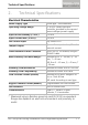
Table Of Contents
- 1. Introduction
- 2. Technical Specifications
- 3. Installation
- 4. Wiring Instructions
- 5. Reader Functionality
- 5.1 Transmit Mode
- 5.2 Programming the AYC-E/Q/T60 Series
- 5.2.1 Entering Programming Mode
- 5.2.2 Exiting Programming Mode
- 5.2.3 Selecting Keypad Transmission Format
- 5.2.4 Keypad Transmission Format Option Number
- 5.2.4.1 Option 1: Single Key, Wiegand 6-Bit (Rosslare Format)
- 5.2.4.2 Option 2: Single Key, Wiegand 6-Bit Nibble and Parities
- 5.2.4.3 Option 3: Single Key, Wiegand 8-Bit Nibbles Complemented
- 5.2.4.4 Option 4: 4 Keys Binary + Facility Code, Wiegand 26-Bit
- 5.2.4.5 Option 5: 1 to 5 Keys + Facility Code, Wiegand 26-Bit
- 5.2.4.6 Option 6: 6 Keys BCD and Parity Bits, Wiegand 26-Bit
- 5.2.4.7 Option 7: Single Key, 3x4 Matrix Keypad (MD-P64)
- 5.2.4.8 Option 8: 1 to 8 Keys BCD, Clock & Data
- 5.2.4.9 Option 9: Single Key, Wiegand 4-Bit
- 5.2.5 Selecting HID Prox Card Transmission Format
- 5.2.6 Selecting Rosslare PROX Card Transmission Format
- 5.2.7 Changing the Programming Code
- 5.2.8 Changing the Facility Code
- 5.2.9 Setting the Backlight Behavior
- 5.2.10 Setting the Reader Format
- 5.2.11 Return to Factory Default Settings
- 5.2.12 Replacing a Lost Programming Code
- 6. Controller Functionality
- 6.1 Normal, Secure, and Master Users
- 6.2 Modes of Operation
- 6.3 Changing the Modes of Operation
- 6.4 Auxiliary Input & Output
- 6.5 Door Alarms
- 6.6 Internal Case and Back Tamper
- 6.7 Lockout Feature (Keypad/Card Tamper)
- 6.8 REX Function
- 6.9 Secured Series Intelligent Power Supply
- 6.10 Programming the AYC-E/Q/T60
- 6.10.1 Entering Programming Mode
- 6.10.2 Exiting Programming Mode
- 6.10.3 Changing Lock Strike Code
- 6.10.4 Changing Auxiliary Code
- 6.10.5 Changing the Programming Code
- 6.10.6 Changing the Normal/Secure Code
- 6.10.7 Changing the Normal/Bypass Code and Door Chime Settings
- 6.10.8 Setting Fail Safe/Secure Operation, Tamper Siren and Lock Strike Release Time
- 6.10.9 Defining the Auxiliary Input and Output
- 6.10.10 Detailed Reference Guide
- 6.10.11 Setting the Lockout Feature
- 6.10.12 Setting the Backlight Behavior
- 6.10.13 Selecting the Rosslare PROX and HID Prox Format
- 6.10.14 Enrolling Primary and Secondary Codes
- 6.10.15 Deleting Primary and Secondary Codes
- 6.10.16 Relay Codes Assignment
- 6.10.17 PIN Code Length/Factory Default Settings
- 6.10.18 Replacing a Lost Programming Code
- 6.10.19 Replacing a Lost Normal/Secure Code

Technical Specifications
AYC-E/Q/T60 Family Installation and Programming Manual 11
2. Technical Specifications
Electrical Characteristics
Power Supply Type
Linear type – recommended
Operating Voltage Range
5–16 VDC (when used as a
controller, provided by the secured
series intelligent power supply)
Input current standby (12 VDC)
110 mA
Input Current Max (16 VDC)
130 mA
LED Control Input
Dry contact N.O.
Tamper Output
Open collector, active low, 32 mA
max sink current
Cable Distance to Host Controller
Up to 500 ft (150 meters) using an
18-AWG cable
Max Proximity Card Read Range*
Rosslare PROX: E – 40 mm, Q – 45
mm, T – 40 mm
HID Prox: E – 40 mm, Q – 45 mm, T
– 30 mm
Proximity Card Modulation
Rosslare PROX/HID Prox at 125 KHz
Proximity Card Compatibility
Rosslare PROX/HID Prox cards
Card Transmit Format (Reader)
Rosslare PROX cards: Wiegand 26-
bit, or Clock & Data
HID cards: According to card type
Keypad Transmit Format (Reader)
Programmable PIN code formats
LED Indicators
Two tri-colored LEDs
Communication
Data1/C1, Data0/C2–open
collector, 5 V termination
* Measured using a Rosslare proximity card (AT-R14) or equivalent.
Range also depends on electrical environment and proximity to
metal.