AY-G/H6xx0 Open to Secure (O2S) Readers Installation and User Manual Models: AY-G6270/G6280 AY-H6270/H6280 AY-H6270/H6280 AY-G6270/G6280 AY-G6370/G6380 AY-H6370/H6380 AY-G6370/G6380 AY-H6370/H6380
Copyright © 2014 by Rosslare. All rights reserved. This manual and the information contained herein are proprietary to ROSSLARE ENTERPRISES LIMITED and/or its related companies and/or subsidiaries’ (hereafter: "ROSSLARE"). Only ROSSLARE and its customers have the right to use the information. No part of this manual may be re-produced or transmitted in any form or by any means, electronic or mechanical, for any purpose, without the express written permission of ROSSLARE.
Table of Contents Table of Contents 1. 1.1 1.2 Introduction ................................................................ 8 Key Features ........................................................................... 8 Box Content ........................................................................... 9 2. Technical Specifications ............................................ 10 3. Mounting ................................................................... 12 4. Wiring Instructions ..............
Table of Contents 7.6 Changing the Programming Code .......................................... 24 7.7 Changing the Facility Code .................................................... 24 7.8 Setting the Backlight Behavior ............................................... 25 7.9 Return to Factory Default Settings .......................................... 26 7.10 Replacing a lost Programming Code ....................................... 26 8. OSDP Operation..............................................
List of Figures List of Figures Figure 1: Mounting..........................................................................................
List of Tables List of Tables Table 1: Wiring ................................................................................................13 Table 2: Reader Programming Menu ...............................................................17 Table 3: Keypad Transmission Format ..............................................................19 Table 4: Bit Description Table ..........................................................................
Introduction Notice and Disclaimer This manual’s sole purpose is to assist installers and/or users in the safe and efficient installation and usage of the system and/or product, and/or software described herein. BEFORE ATTEMPTING TO INSTALL AND/OR USE THE SYSTEM, THE INSTALLER AND THE USER MUST READ THIS MANUAL AND BECOME FAMILIAR WITH ALL SAFETY REQUIREMENTS AND OPERATING PROCEDURES. The system must not be used for purposes other than those for which it was designed.
Introduction 1. Introduction The Open to Secure (O2S) family of readers are multi-format contactless smart card readers for use in access control system solutions. The AY-x6x70 readers support reading O2S ID data and the CSN from MIFARE Plus® and MIFARE® Classic credentials. The AY-x6x80 readers support reading O2S ID Data and the CSN from MIFARE® DESFire® EV1 and MIFARE Classic credentials. O2S ID data is stored in the secure memory of the MIFARE credential.
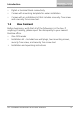
Introduction Pigtail or terminal block connectivity Comes with mounting template for easier installation Comes with an installation kit that includes a security Trox screw and a security Torx screw tool. 1.2 Box Content Before beginning, verify that all of the following is in the box. If anything is missing, please report the discrepancy to your nearest Rosslare office.
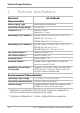
Technical Specifications 2. Technical Specifications Electrical Characteristics AY-G H6xx0 Power Supply Type Linear type (recommended) Operating Voltage Range 6 to 16 VDC Current @ 12 V Standby: 85 mA Maximum: 110 mA Read Range for G Models* MIFARE Classic: 40 to 45 mm (1.5 to 1.8 in.) MIFARE Plus: 25 mm (1 in.) MIFARE DESFire EV1: 25 mm (1 in.) Read Range for H Models* MIFARE Classic: 40 to 45 mm (1.5 to 1.8 in.) MIFARE Plus: 30 mm (1.2 in.) MIFARE DESFire EV1: 30 mm (1.2 in.
Technical Specifications Physical Characteristics Dimensions of Pigtail Models (H x W x D) Dimensions of Terminal Block and OSDP Models (H x W x D) Weight AY-G6xx0: 145.3 x 42.0 x 23.0 mm (5.7 x 1.7 x 0.9 in.) AY-H6xx0: 120.0 x 80.0 x 23.0 mm (4.7 x 3.2 x 0.9 in.) AY-G6xx0: 145.3 x 42.0 x 31.0 mm (5.7 x 1.7 x 1.2 in.) AY-H6xx0: 120.0 x 80.0 x 31.0 mm (4.7 x 3.2 x 1.2 in.) AY-G6xx0: 155 g (5.5 oz) AY-H6xx0: 217.0 g (7.
Mounting 3. Mounting To mount the units: 1. Determine an approximate location for the reader. 2. Peel off the back of the self-adhesive mounting label template and place it at the required mounting location. 3. Using the template as a guide, drill two holes (sizes indicated on the template) used for mounting the back plate onto the surface (Figure 1). Figure 1: Mounting AY-GXXXX AY-HXXXX 4. Insert a suitable wall plug into each screw hole. 5. Drill a 10-mm (7/16”) hole for the cable. 6.
Wiring Instructions 4. Wiring Instructions The units are supplied with a 10-conductor 18” (46 cm) pigtail or with 10 terminal blocks. To connect a pigtail reader to the controller: 1. Prepare the reader cable by cutting its jacket back 3.2 cm (1¼”) and strip the insulation from the wires 1.3 cm (½"). 2. Prepare the controller cable by cutting its jacket back 3.2 cm (1¼") and strip the insulation from the wires 1.3 cm (½"). 3.
Wiring Instructions • The individual wires from the reader are color coded according the Wiegand standard. • When using a separate power supply for the reader, this supply and that of the controller must have a common ground. • The reader’s cable shield wire should be preferably attached to an earth ground, or a signal ground connection at the panel, or power supply end of the cable. This configuration is best for shielding the reader cable from external interference.
Reader Operation 5. Reader Operation Once the reader is wired to a power supply and to the controller, you should test the reader. To test the reader: 1. Power up the reader. The beeper sounds three times and the LED turns red, blue, and green, to indicate that the reader is working properly. The LED returns to its Standby mode (red for the AY-x6x70 series and blue for the AY-x6x80 series). 2. Present the appropriate type of proximity card to the reader or enter a valid keypad entry.
Proximity Operation 6. Proximity Operation 6.1 Supported Credential Technologies O2S readers support reading from the secure memory of the following credential technologies: AY-H6x80 and AY-G6x80 MIFARE DESFire EV1 (2K, 4K, 8K) MIFARE Classic (1K, 4K) AY-H6x70 and AY-G6x70 6.2 MIFARE Plus X (2K, 4K) MIFARE Plus S (2K, 4K) MIFARE Classic (1K, 4K) Wiegand Output For O2S credentials, the reader outputs the ID data stored in the secure memory (sector/file) of the credential.
Keypad Operation Instructions 7. Keypad Operation Instructions This chapter is relevant to models AY-G63x0 and AY-H63x0. 7.1 Programming Menu Some but not all of the reader options can be programmed using the unit's keypad driven Programming Menu System. During the unit’s manufacturing process, certain codes and settings are preprogrammed. These settings are called the default factory settings. Table 2 shows the names of all the menus. Default factory settings are marked by *.
Keypad Operation Instructions 7.2 Entering Programming Mode To reach the Programming Menu System, the unit must first be placed into Programming mode. To enter Programming mode: 1. Press # four times. The yellow LED blinks. 2. Enter your Programming code. If the Programming code is valid, and the unit is in Programming mode and the yellow LED is lit. 7.3 • The factory 4-digit Programming code is 1234. • If a Programming code is not entered within 30 seconds, the unit returns to Standby mode.
Keypad Operation Instructions 3. Enter the appropriate option number for the keypad transmission format that you wish to select (see Table 3). If an incorrect option number is entered, the reader returns to Standby mode and the keypad transmission format remains unchanged. The system returns to Standby mode. You hear three beeps and the green LED blinks. 7.5 • Only one keypad transmission format can be active at any one time.
Keypad Operation Instructions 7.5.1 Option 1: Single Key, Wiegand 6-Bit (Rosslare Format) Each key press immediately sends 4 bits with 2 parity bits added – even parity for the first 3 bits and odd parity for the last 3 bits. 0 = 1 1010 0 ="A" in Hexadecimal 1 = 0 0001 0 2 = 0 0010 0 3 = 0 0011 1 4 = 1 0100 1 5 = 1 0101 0 7.5.
Keypad Operation Instructions 7.5.4 Option 4: 4 Keys Binary + Facility Code, Wiegand 26-Bit This option buffers 4 keys and outputs keypad data with a 3-digit Facility code like a standard 26-bit card output. The Facility code is set in Programming Menu 4 and can be in the range 000 to 255. The factory default setting for the Facility code is 000 (see Section 7.7 for more information). The keypad PIN code is 4 digits in length and can range between 0000 and 9999.
Keypad Operation Instructions When entering a keypad PIN code that is less than 5 digits in length, # must be pressed to signify the end of PIN code entry. For keypad PIN codes that are 5 digits in length, on the fifth key press of the 5-digit PIN code, the data is sent across the Wiegand Data lines as binary data in the same format as a 26-bit card.
Keypad Operation Instructions Where: EP = Even parity for first 12 bits OP = Odd parity for last 12 bits A = The first key entered B = Second key entered C = Third key entered 7.5.7 D = Fourth key entered E = Fifth key entered F = Sixth key entered Option 8: 1 to 8 Keys BCD, Clock & Data Option 8 buffers up to 8 keys and outputs keypad data without a Facility code like standard Clock and Data card output. The keypad PIN code can be one to eight digits in length.
Keypad Operation Instructions 7.5.8 Option 9: Single Key, Wiegand 4-Bit With this option, each key press immediately sends 4 bits of data, with no parity bits added. 0 = 0000 1 = 0001 2 = 0010 3 = 0011 4 = 0100 5 = 0101 7.6 6 = 0110 7 = 0111 8 = 1000 9 = 1001 *= 1010 ="A" in Hexadecimal #=1011 ="B" in Hexadecimal Changing the Programming Code To change the Programming code: 1. Enter Programming mode. 2. Press 3 to enter Menu 3. The green LED blinks. 3.
Keypad Operation Instructions The system returns to Standby mode. You hear three beeps and the green LED blinks 7.8 • The Facility code can be in the range of 000 to 255. • The default Facility code is 0. Setting the Backlight Behavior To set the backlight behavior: 1. Enter Programming mode. 2. Press 6 to enter Menu 6. The green LED blinks. 3.
Keypad Operation Instructions 7.9 Return to Factory Default Settings You must be very careful before using this command! This erases the entire memory and returns all codes to their factory default setting. To return to factory default settings: 1. Enter Programming mode. 2. Press 0 to enter Menu 0. The white LED blinks. 3. Enter your Programming code. If the Programming code is valid, all memory is erased, you hear three beeps and the controller returns to Standby mode.
OSDP Operation 8. OSDP Operation Rosslare O2S readers that support OSDP operation are compatible with most OSDP commands. The reader address is set using DIP switches on the back of the reader.
Wiegand Output Formats A. Wiegand Output Formats The AY-G/H6xx0 can read all Rosslare O2S cards/tags and outputs card ID data in Wiegand format according to the number of bits stored in the secured memory area on the card. The readers support any O2S card from 26-bit to 128-bit. For more details on supported formats and custom formats, contact your Rosslare Sales representative.
Wiegand Output Formats A.
Wiegand Output Formats Example: FC=59, ID=21,003 30 AY-G/H6xx0 Installation and User Manual
Wiegand Output Formats A.
Wiegand Output Formats Example: ISSUE No=0, FC=905, Site Code=103, ID=9,029 32 AY-G/H6xx0 Installation and User Manual
Limited Warranty B. Limited Warranty The full ROSSLARE Limited Warranty Statement is available in the Quick Links section on the ROSSLARE website at www.rosslaresecurity.com. Rosslare considers any use of this product as agreement to the Warranty Terms even if you do not review them. FCC NOTE: This device complies with Part 15 of the FCC Rules.
AY-G6xx0 and AY-H6xx0 Asia Pacific, Middle East, Africa Rosslare Enterprises Ltd. Kowloon Bay, Hong Kong Tel: +852-2795-5630 Fax: +852-2795-1508 support.apac@rosslaresecurity.com United States and Canada Rosslare Security Products, Inc. Southlake, TX, USA Toll Free: +1-866-632-1101 Local: +1-817-305-0006 Fax: +1-817-305-0069 support.na@rosslaresecurity.com Europe Latin America Rosslare Latin America Buenos Aires, Argentina Tel: +54-11-4001-3104 support.la@rosslaresecurity.