AY-H6355BT CSN SMART™ Smart Card Readers (Rev. A) Installation and User Manual BLE 4.
Copyright © 2017 by Rosslare. All rights reserved. This manual and the information contained herein are proprietary to ROSSLARE ENTERPRISES LIMITED and/or its related companies and/or subsidiaries’ (hereafter: "ROSSLARE"). Only ROSSLARE and its customers have the right to use the information. No part of this manual may be re-produced or transmitted in any form or by any means, electronic or mechanical, for any purpose, without the express written permission of ROSSLARE.
Table of Contents Table of Contents 1. Introduction ................................................................ 7 1.1 Installation Kit ......................................................................... 8 2. Technical Specifications .............................................. 9 3. Mounting ................................................................... 10 4. Wiring Instructions ................................................... 12 5. OSDP Operation.............................
List of Figures List of Figures Figure 1: Removing the Top Cover ..................................................................10 Figure 2: DIP Switch Compartment..................................................................15 Figure 3: DIP Switch Settings ...........................................................................
List of Tables List of Tables Table 1: Wiring the Unit as a Reader to a Control Panel ..................................12 Table 2: Reader Programming Menus ..............................................................18 Table 3: Keypad Transmission Format Option Number ....................................21 Table 4: Proximity Card Transmission Format Option Number .........................
Introduction Notice and Disclaimer This manual’s sole purpose is to assist installers and/or users in the safe and efficient installation and usage of the system and/or product, and/or software described herein. BEFORE ATTEMPTING TO INSTALL AND/OR USE THE SYSTEM, THE INSTALLER AND THE USER MUST READ THIS MANUAL AND BECOME FAMILIAR WITH ALL SAFETY REQUIREMENTS AND OPERATING PROCEDURES. The system must not be used for purposes other than those for which it was designed.
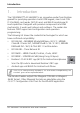
Introduction 1. Introduction The CSN SMART™ AY-H6355BT is an innovative reader from Rosslare geared for quad-play operation: backlit PIN keypad, smart card CSN (13.56 MHz) card reader, NFC-ID read, and BLE-ID smartphone ID read capabilities. Designed with premium components and IP65 mechanicals, it works well indoors and outdoors. The reader also features OSDP support and configuration card operation programming.
Introduction 1.
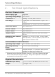
Technical Specifications 2. Technical Specifications Electrical Characteristics Power Supply Type Regulated Operating Voltage Range 8 to 16 VDC Current @ 12 V Standby: 120 mA, max: 220 mA Read Range* Contactless 13.56 MHz and NFC: Up to 7 cm (2.8 in.) Green LED Control Dry Contact, N.O. Red LED Control Dry Contact, N.O. Buzzer Control Dry Contact, N.O. Tamper Output Open collector, active low, max.
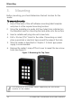
Mounting 3. Mounting Before mounting, you should determine the best location for the reader. To mount the units: 1. Peel off the back of the self-adhesive mounting label template and place it at the required mounting location. 2. Using the template as a guide, drill two holes (sizes indicated on the template) used for mounting the back plate onto the surface. 3. Insert a suitable wall plug into each screw hole. 4. Drill a 10-mm (7/16”) hole for the cable.
Mounting 7. Align the two holes of the reader with those drilled in the wall and firmly attach the reader to the wall with two screws, whose size is indicated on the template. 8. Relocate the front cover onto the reader. The reader can also be mounted using strong epoxy glue.
Wiring Instructions 4. Wiring Instructions The units are supplied with a 10-conductor 5-m (16-ft) pigtail with exposed wires coated with solder. To connect the unit as a reader to an access control unit: 1. Select the appropriate connections according to Table 1. 2. Prepare the controller cable by cutting its jacket back about 3 cm (1¼") and strip the insulation from the wires about 1.3 cm (½"). 3.
Wiring Instructions 4. Trim and insulate the ends of all unused conductors individually. Do not short any unused wires together. • The individual wires from the reader are color coded according the Wiegand standard. • When using a separate power supply for the reader, this supply and that of the controller must have a common ground. • The reader’s cable shield wire should be preferably attached to an earth ground, or a signal ground connection at the panel, or the power supply end of the cable.
OSDP Operation 5. OSDP Operation • In OSDP mode, all control lines (Inputs/Outputs) are disabled. • In OSDP mode, if a connection is not established or lost with the controller, the right LED flashes yellow continuously. The reader is compatible with all reader-related OSDP commands. The reader address is set using DIP switches on the back of the reader. Release the screw on the back of the reader to remove the door to access the DIP switches (Figure 2).
OSDP Operation Figure 2: DIP Switch Compartment AY-H6355BT Installation and User Manual 15
OSDP Operation Figure 3 shows the DIP switch settings, which are also described below. Figure 3: DIP Switch Settings DIP Switch 1 This switch is used to select the reader output (Wiegand or OSDP): Off = Wiegand On = OSDP DIP Switch 2 This switch is reserved for future use. DIP Switch 3 This switch is reserved for future use. DIP Switches 4 to 8 These switches set the address of the reader for OSDP protocol. DIP Switch 4 is MSB and DIP Switch 8 is LSB. The address is the DIP switch state +1.
Reader Functionality 6. Reader Functionality Upon power on, the unit flashes yellow, then blue, and then orange, each for 1 second and a beep is heard for each color. 6.1 Standby Mode The default mode of the reader is Standby mode. In Standby mode, the unit is ready to receive data from an entered PIN code or from a presented proximity card, NFC-ID, and BLE-ID. When the reader is in Standby mode, both LEDs are blue.
Reader Functionality Table 2: Reader Programming Menus Menu Description 1 2 Default Selecting Keypad Transmission Format Single Key, 6-Bit Wiegand (Rosslare Format) Single Key, 6-Bit Wiegand with Nibble + Parity Bits Single Key, 8-Bit Wiegand, Nibbles Complemented 4 Keys Binary + Facility Code, Wiegand 26-Bit 1 to 5 Keys + Facility Code, Wiegand 26-Bit 6 Keys BCD and Parity Bits, Wiegand 26-Bit 1 to 8 Keys BCD, Clock & Data Single Key, Wiegand 4-Bit Selecting Card Transmission Format Wiegand 26-Bit Cloc
Reader Functionality 6.2.1 Entering Programming Mode To reach the Programming Menu System, the unit must first be placed into Programming mode. • The factory 4-digit Programming code is 1234. • If a Programming code is not entered within 20 seconds, the unit returns to Standby mode. To enter Programming mode: 1. Press # four times. The left LED turns yellow and the right LED turns off. yellow 2. Enter your 4-digit Programming code. If the Programming code is valid, the left LED turns green.
Reader Functionality 6.2.3 Selecting Keypad Transmission Format The AYC-x6355 has nine different keypad transmission formats. See Table 3 in Section 6.2.3.1 for more information on keypad transmission formats. • Only one keypad transmission format can be active at any one time. • When using the keypad transmission format "1 to 8 keys BCD, Clock & Data" (Option 8), an additional input is required to specify the number of keys in the PIN code. To select the key pad transmission format: 1.
Reader Functionality 6.2.3.1 Keypad Transmission Format Option Number Table 3 presents the eight different keypad transmission formats.
Reader Functionality Option 2: Single Key, Wiegand 6-Bit Nibble and Parities Each key press immediately sends 4 bits with 2 parity bits added – even parity for the first 3 bits and odd parity for the last 3 bits.
Reader Functionality If the entry of the 4-digit keypad PIN code is disrupted and no number key is pressed within 5 seconds, the keypad clears the PIN code entry buffer, generates a beep and is ready to receive a new 4-digit keypad PIN code.
Reader Functionality (EP) FFFF FFFF AAAA AAAA AAAA AAAA (OP) Where: EP = Even parity for first 12 bits OP = Odd parity for last 12 bits F = 8-bit Facility code A = 16-bit code generated from keypad Option 6: 6 Keys BCD and Parity Bits, Wiegand 26-Bit Option 6 sends buffer of 6 keys, adds parity and sends a 26-Bit Binary BCD message. Each key is a four bit equivalent of the decimal number. The keypad PIN code must be 6 key presses long.
Reader Functionality the PIN code. The data is sent across the two data output lines as binary data in Clock & Data format. If * or # key is pressed during PIN code entry, the keypad clears the PIN code entry buffer, generates a beep, and is ready to receive a new keypad PIN code.
Reader Functionality 3. Enter the appropriate option number for the proxy card transmission format that you wish to select: 1 – Wiegand 26-Bit 2 – Clock & Data 3 – Wiegand 32-Bit 4 – Wiegand 32-Bit Reversed Byte 5 – Wiegand 34-Bit 6 – Wiegand 40-Bit 7 – Wiegand 56-Bit 8 – Wiegand 64-Bit You hear three beeps. The system returns to Standby mode. 6.2.4.
Reader Functionality Option 1: Wiegand 26-Bit In this mode, 3 LSB bytes from the card serial number (UID) are transmitted in Wiegand 26-Bit format. Two parity bits are added. An even parity bit is sent first, followed by three bytes of card data, and by an odd parity bit.
Reader Functionality Where: D = 1st (LSB) byte of card serial number C = 2nd byte of card serial number B = 3rd byte of card serial number A = 4th (MSB) byte of card serial number Option 5: Wiegand 34-Bit In this mode, 4 LSB bytes of card serial number are transmitted in Wiegand 34-Bit format. Bytes are sent in reversed order. The LSB part of the card serial number is sent first and the MSB byte is sent last. An even parity is sent first, followed by 32-Bit data and an odd parity bit.
Reader Functionality Option 7: Wiegand 56-Bit In this mode, 7 bytes of card serial number are transmitted in Wiegand 56-Bit format. No parity bits are added. AAAA AAAA BBBBBBBB CCCCCCCC DDDDDDDD EEEEEEEE FFFFFFFF GGGGGGGG Option 8: Wiegand 64-Bit In this mode, 8 bytes of card serial number are transmitted in Wiegand 64-Bit format. No parity bits are added. AAAA AAAA BBBBBBBB CCCCCCCC DDDDDDDD EEEEEEEE FFFFFFFF GGGGGGGG HHHHHHHH 6.2.
Reader Functionality 6.2.6 Changing the Facility Code • The Facility code can be in the range of 000 to 255. • The default Facility code is 0. To change the Facility code: 1. Enter Programming mode. green 2. Press 4 to enter Menu 4. The right LED turns yellow. green yellow 3. Enter the new 3-digit code you wish to set as the Facility code. You hear three beeps. The system returns to Standby mode. 6.2.7 blue blue Selecting Credential Technology To select the credential technology : 1.
Reader Functionality 3. Enter one of the following codes: 0 – All formats (default) 1 – 14443A 2 – 14443B 3 – 15693 4 – Felica 5 – China ID 6 – Topaz You hear three beeps. The system returns to Standby mode. 6.2.8 blue blue Setting the Backlight Behavior To set the backlight behavior: 1. Enter Programming mode. green 2. Press 6 to enter Menu 6. The right LED turns yellow. green yellow 3.
Reader Functionality 6.2.9 Return to Factory Default Settings You must be very careful before using this command! This erases the entire memory and return all codes to their factory default setting. To return to factory default settings: 1. Enter Programming mode. green 2. Press 0 to enter Menu 0. Both LEDs flash red. red red 3. Enter your 4-digit Programming code. If the Programming code is valid, all memory is erased. You hear three beeps and the reader returns to Standby mode.
Declaration of Conformity A. Declaration of Conformity This device complies with Part 15 of the FCC Rules. Operation is subject to the following two conditions: This device may not cause harmful interference. This device must accept any interference received, including interference that may cause undesired operation. Changes or modifications not expressly approved by the party responsible for compliance could void the user's authority to operate the equipment.
Limited Warranty B. Limited Warranty The full ROSSLARE Limited Warranty Statement is available in the Quick Links section on the ROSSLARE website at www.rosslaresecurity.com. Rosslare considers any use of this product as agreement to the Warranty Terms even if you do not review them.
AY-H6355BT Asia Pacific, Middle East, Africa Rosslare Enterprises Ltd. Kowloon Bay, Hong Kong Tel: +852-2795-5630 Fax: +852-2795-1508 support.apac@rosslaresecurity.com United States and Canada Rosslare Security Products, Inc. Southlake, TX, USA Toll Free: +1-866-632-1101 Local: +1-817-305-0006 Fax: +1-817-305-0069 support.na@rosslaresecurity.com Europe Latin America Rosslare Latin America Buenos Aires, Argentina Tel: +54-11-4001-3104 support.la@rosslaresecurity.