
Technical Specs

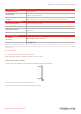


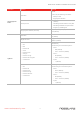

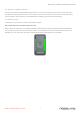
Table Of Contents

4. Mount the reader on the bracket and fasten at bottom with Torx screw and Torx screwdriver provided.
3.2. Wiring the M ulti-Smart™ R eaders
To Wire Multi-Smart™ Readers:
Units are supplied with a 11conductor 56cm (22in.) pigtail with exposed wires coated with solder.
•
The individual wires from the reader are color coded according the Wiegand standard.
•
When using a separate power supply for the reader, this supply and that of the controller must have a
common ground.
•
The reader’s cable shield wire should be preferably attached to an earth ground, or a signal ground
connection at the panel, or power supply end of the cable.
To Connect The Reader To The Controller:
1. Select the appropriate connections according to the table below.
2. Prepare the controller cable by cutting its jacket back about 3 cm (1¼ in.) and strip the insulation from the wires
about 1.3 cm (½ in.).
3. Splice the reader’s pigtail wires to the corresponding controller wires and cover each joint with insulating tape.
4. If the tamper output is being utilized, connect the purple wire to the correct input on the controller.
5. Trim and insulate the ends of all unused conductors individually. Do not short any unused wires together.
Multi-Smart™ Readers Installation & User Guide
www.rosslaresecurity.com
3