
User's Manual


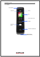


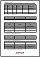

Table Of Contents
- 1.2.3.1. Cable & Connector
- 1.2.3.2. Pin Details
- 1.2.3.3. Terminal <- > MCP040 wiring
- 1.2.3.4. Terminal <- > LC015B wiring
- 1.2.3.5. Terminal <- > EM Type Door Lock wiring
- 1.2.3.6. Terminal <- > WIEGAND Device wiring
- 3.1.6.1. Single Type (Door Lock=STRIKE)
- 3.1.6.2. Single Type (Door Lock=MOTOR)
- 3.1.6.3. Single Type (Lock Controller=LC010)
- 3.1.6.4. Single Type (Lock Controller=LC015)
- 3.1.6.5. Dummy Type (RS485=MCP040)
- 3.1.6.6. Network Type (Door Lock=STRIKE)
- 3.1.6.7. Network Type (Door Lock=MOTOR)
- 3.1.6.8. Network Type (Lock Controller=LC010)
- 3.1.6.9. Network Type (Lock Controller=LC015)
- 3.4.1.1. USER TYPE
- 3.4.1.2. AUTH TYPE
- 3.4.1.3. INPUT FP
- 3.4.1.4. INPUT CARD
- 3.4.2.1. AUTO ADD – 1. FP
- 3.4.2.2. AUTO ADD
- 3.6.1.1. TYPE
- 3.6.1.2. AUTO TNA
- 3.6.2.1. Language
- 3.6.2.2. SHOW ID
- 3.6.2.3. USER LOGO
- 3.6.2.4. USER ID LEN
- 3.6.2.5. DATE
- 3.6.3.1. LOG SAVE
- 3.6.3.2. IMAGE SAVE
- 3.6.4.1. RESULT
- 3.6.4.2. NET ERROR
- 3.6.4.3. PING
- 3.7.1.1. 1:1 LEVEL
- 3.7.1.2. 1: N LEVEL
- 3.7.1.3. LFD LEVEL
- 3.7.1.4. AUTH TIME
- 3.8.1.1. LOCK1 type
- 3.8.1.2. LOCK1 OPEN TIME
- 3.8.1.3. LOCK2 type
- 3.8.1.4. LOCK2 OPEN TIME
- 3.8.1.5. OPEN ALARM
- 3.8.1.6. DM0
- 3.8.1.7. DM1
- 3.8.1.8. DM2
- 3.8.2.1. TYPE
- 3.8.2.2. DEV ID
- 3.8.3.1. WIRE-INPUT
- 3.8.3.2. WIRE-OUTPUT
- 3.8.3.3. CUSTOM BIT LENGTH
- 3.8.3.4. SITE CODE
- 3.8.3.5. SEND INFO
- 3.10.1.1. CONFIG
- 3.10.1.2. LOG DB INIT
- 3.10.1.3. FACTORY INIT
- 3.10.2.1. INT DEVICE
- 3.10.2.2. EXT DEVICE
- 3.10.3.1. LOG EXPORT
- 3.10.3.2. USER EXPORT
- 3.10.3.3. USER INPUT
- 3.10.3.4. FW UPDATE

AY-B9250BT User Guide 10
1.3.1. Initial Screen
When powering on at first, the screen is displayed as follow.
1.3.2. Icons
Server connection
State
NONE : No use network
: LAN line is disconnected.
: LAN line is connected (only link is connected)
: Connected with server
Gate
State
: Gate is closed.
: Gate is opened
: Gate is opened forcedly (unusual door open state)
: Gate communication problem
Warning signal
State
NONE : Normal
: Terminal Disassembly State
Fire detection
State
NONE
: Normal
: Sensed by fire detector (valid on DM2 fire set)
BLE connection
State
NONE : Disconnected with Admin App
: Connected with Admin App
MCP040 connection
State
NONE : MCP040 is not used (Normal state)
: MCP040 Mode and bad communication state
: MCP040 Mode and normal communication state
UDL connection
State
NONE : UDL is not used (Normal state)
: UDL is connected
1.3.3. Function KEY
Icon Meaning Function Key Explanation
UP F1 Move cursor up
DOWN F3 Move cursor down
LEFT F2 Move cursor to left
ESC F2 long Move to upper menu
RIGHT
F4
Move cursor to right
ENTER
F4 long or
Move to submenu
State icon
Operation Mode
TNA Mode
Date and Time