ROSSLARE ROSSLA R E www.rosslare.com.
Introduction Contents INTRODUCTION 3 4 5 Technical Specifications Key Features INSTALLATION Mounting the AC-D31 Controller Wiring Diagrams The AC-D31 is a keypad access control unit. The unit accepts up to 500 users and provides entry via the use of PIN codes.
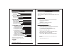
Technical Specification Key Features Here are some of the AC-D31’s key features: Electrical Characteristics Operating Voltage Range: 12 to 16V DC From a Regulated Power Supply Maximum Input Current: Standby: 20mA Max: 60mA Relay Outputs: Lock Strike Relay Not including attached devices Not including attached devices Electronic, 3.5A with built in suppressor protection Form C, 1A Auxiliary Relay Inputs: REX N.O., Dry Contact Auxiliary Input (In / Monitor) N.C., Dry Contact in Monitor Mode N.O.
Installation Terminal Blocks Mounting the AC-D31 Controller 1) Before starting, select the location to mount the AC-D31 controller. This location should be at shoulder height and on the same side as the door handle. Mounting Hole 2) The AC-D31 is designed to be easily mounted to a US Gang Box. Remove the Bezel Screw.
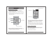
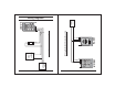
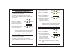
8 0 7 AC-D31 9 # 5 (+) (-) Door 3 6 2 1 4 BL-D40 Wiring the Lock Strike Relay and REX (+) (-) Lock REX / BL (-) ELECTRIC LOCK STRIKE 12V - 16V DC COMMON POWER SUPPLY Mode (+) (-) 12V - 16V DC COMMON POWER SUPPLY 3 FAIL SAFE or FAIL SECURE (+) (-) 6 (-) 06/01 Page 9 AC-D31 (+) (-) 5 2 9 1 # 4 0 8 Lock 06/01 REX / BL Mode Door 7 AC-D31 REX / BL REX Page 8 AC-D31 Wiring the BL-D40 External Sounder Wiring Diagrams REX / BL
Modes of Operation Normal, Secure, & Master Users The AC-D31 accepts up to 500 users and provides entry via the use of PIN codes. Each user is provided with two code memory slots, Memory Slot 1 (Primary Code) and Memory Slot 2 (Secondary Code). The way in which the two memory slots are programmed determines a users access level and also determines the way in which the AC-D31 grants access in its three Modes of Operation.
Changing from Normal Mode to Bypass Mode: Changing the Modes of Operation See Page 20 to create / modify the Normal / Bypass Code Changing from Normal Mode to Secure Mode: 1) Enter the 4-digit Normal / Bypass Code. The default factory setting for the Normal / Secure Code is 3838 1) Enter the 4-digit Normal / Secure Code ! Mode LED will flash red Mode Door Mode Door Mode Door AC-D31 Page 12 2) Press the "#" key to confirm the Mode change.
Request to Exit (REX) Button BL-D40 External Sounder The REX button must be located inside the premises to be secured and is used to open the door without the use of a proximity card or PIN code, it is usually located in a convenient location, e.g. Inside the door or at a receptionist's desk. The function of the REX button depends on whether the Lock Strike Relay is programmed for Fail Safe Operation or Fail Secure Operation.
Programming the AC-D31 Entering Programming Mode Programming the AC-D31 is done solely via the unit's keypad driven Programming Menu System. To reach the Programming Menu System the AC-D31 must first be placed into Programming Mode. See "Entering Programming Mode" on Page 17 for more information. During the AC-D31's manufacturing process certain codes and settings are pre-programmed. These settings are the called the "Default Factory Settings". The table below shows the names of all the AC-D31 Menus.
1) Enter Programming Mode Changing the Open Code 1 Mode The Open Code 1 is mainly used as a method to quickly test the Lock Strike Relay during installation. 2) Press "2" to enter Menu 2 ! The Mode LED will turn red The Default Factory Setting for the Open Code 1 is 2580. When the first user is added to the controller, the default Open Code will automatically be deleted, ready for a new Open Code 1 to be re-entered. 3) Enter the new 4-digit code you wish to set as Open Code 2.
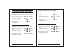
Changing the Normal / Secure Code 1) Enter Programming Mode Mode Door GREEN 2) Press "4" to enter Menu 4 ! The Mode LED will flash red 3) Enter the new 4-digit code you wish to set as Normal / Secure Code 4) System returns to Normal Mode ! You will hear three beeps ! The Door LED will turn off ! The Mode LED will turn green Mode ? ? 0 Enter the 4-digit code 0000 0 Enter the 4-digit code 0001 GREEN ? 0 0 0 0 1 ? 0 ? 0 c) Enable Bypass Code - Disable Door Chime ? Enter any 4-digit code
Setting Fail Safe/Secure Operation Setting Tamper Siren Time Setting the Lock Strike Release Time 1) Enter Programming Mode Mode Door GREEN 2) Press "6" to enter Menu 6 ! The Mode LED will flash green 3) Construct the 4-digit code using the instructions below: Mode Door GREEN ? ? GREEN ? ? Enrolling Primary & Secondary Codes Primary Codes - Primary Codes can only be enrolled to an empty User Slot, i.e a slot where there is no existing Primary Code. - Primary Codes must be unique, i.e.
Enrolling Primary and Secondary Codes using the Standard Method Mode 1) Enter Programming Mode Enrolling Secondary Codes using the Code Search Method Door The Code Search feature enables you to quickly enroll a Secondary Code to a user who already has a Primary Code. Door 1) Enter Programming Mode GREEN 2) Press "7" to enter Menu 7 ! The Door LED will turn orange Mode 3) Enter the 3-digit User Slot number ? ? between 001 to 500 that you wish to enroll a Primary or Secondary code to.
Deleting Primary & Secondary Codes Deleting Primary and Secondary Codes using the Code Search Method There are two methods to delete Primary and Secondary codes, the Standard Method and the Code Search Method. 1) Enter Programming Mode When deleting a User Slot, both the Primary Code and the Secondary code are erased.
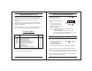
Return To Factory Default Settings Warning: You must be very careful before using this command! Doing so will erase the entire memory which includes all User and Special Codes, and return all codes to their factory defaut settings. Mode 1) Enter Programming Mode Door 3) Enter your 4-digit Programming Code. Mode Door RED ? ? RED ? Note: The AC-D31 must be in Normal Mode otherwise this will not work. Make sure that the Mode LED is green before proceeding.
Glossary A Access Control: Primarily refers to a device or set of devices controlling the entry of people traveling through a door or set of doors. Amplitude Shift Keying (ASK): The type of data communications between the Proximity Card and the Proximity Reader. ASK: An abbreviation of "Amplitude Shift Keying". B Back Tamper: The electronic tamper signal advising the controller that the controller has been removed from the wall.
Technical Support International Web Site: http:///www.rosslare.com.hk/support/ Asia, Australia, & South America: Rosslare Enterprises Ltd. 905-912 Wing Fat Industrial Bldg., 12 Wang Tai Road, Kowloon Bay, Hong Kong. Tel: Fax: E-mail: (852) 2795 5630 (852) 2795 1508 info@rosslare.com.hk Europe, Russia, Middle East, Africa: Rosslare Security Products S.r.l Via F.lli Gabba 5, 20121 Milano, Italy Tel: Fax: E-mail: (39) 0382 24800 (39) 0382 24800 marco.rogante@tin.it rosslarect@aol.