
Programming Manual
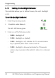
Table Of Contents
- 1. Introduction
- 2. Technical Specifications
- 3. Installation
- 4. Operation
- 5. Programming
- 5.1 Entering the Programming Mode
- 5.2 Exiting the Programming Mode
- 5.3 Changing the Open Code
- 5.4 Changing the Auxiliary Code
- 5.5 Changing the Programming Code
- 5.6 Changing the Normal/Secure Code
- 5.7 Changing the Normal/Bypass Code
- 5.8 Setting Fail Safe/Secure Operation
- 5.9 Setting Auxiliary Modes
- 5.10 Setting the Lockout Feature
- 5.11 Setting the Backlight Behavior
- 5.12 Enrolling Primary and Secondary Codes
- 5.13 Deleting Primary and Secondary Codes
- 5.14 Relay Codes Assignment
- 5.15 Changing PIN Code Length/Factory Default Settings
- 5.16 Replacing a Programming Code
- 5.17 Replacing a Normal/Secure Code
- A. Declaration of Conformity
- B. Limited Warranty

Programming
50 AC-F/G4x Series Installation and Programming Manual
5.9.10 Auxiliary Mode 9
This mode control
s the door indicator (right LED).
The
right LED is not lit when:
•
A valid code is entered
•
While in Secure mode when waiting for Secondary code.
Auxiliary input function: Red LED control
Auxiliary output activated by: Valid user code, Auxiliary code
For example, in Auxiliary Mode 9, the controller can function as a
2-door controller and also provide LED indicator functionality
control. The auxiliary relay is connected to the lock on the
second door. The auxiliary setting defines the Door Open time
for the second door. The auxiliary input is used to control the
door indicator (right LED). If the auxiliary input is open, the right
LED flashes red; if the auxiliary input is closed the right LED
flashes green.
5.10
Setting the Lockout Feature
If the controller is presented with wrong codes (PIN or card)
consecutively several times, the unit goes into Lockout mode.
When a lockout occurs, the controller keypad and reader are
locked so no codes can be entered until the set lockout period
expires. During Lockout, the left LED is Off, the right LED flashes