
Programming Manual
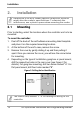
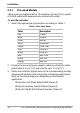

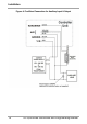
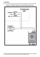
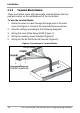

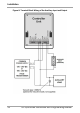
Table Of Contents
- 1. Introduction
- 2. Installation
- 3. Operation
- 4. Programming
- 4.1 Entering the Programming Mode
- 4.2 Exiting the Programming Mode
- 4.3 Changing the Open Code
- 4.4 Changing the Auxiliary Code
- 4.5 Changing the Programming Code
- 4.6 Changing the Normal/Secure Code
- 4.7 Changing the Normal/Bypass Code
- 4.8 Setting Fail Safe/Secure Operation, Tamper Siren and Lock Strike Release Time
- 4.9 Setting Auxiliary Modes
- 4.10 Keypad Heater Operation
- 4.11 Setting the Lockout Feature
- 4.12 Setting the Backlight Behavior
- 4.13 Enrolling Primary and Secondary Codes
- 4.14 Deleting Primary and Secondary Codes
- 4.15 Relay Codes Assignment
- 4.16 Changing PIN Code Length/Factory Default Settings
- 4.17 Replacing a Programming Code
- 4.18 Replacing a Normal/Secure Code
- 5. Technical Specifications

Installation
14 AC-Q4x Series Installation and Programming Manual
2.2.1 Pre-wired Models
These units are supplied with a 10-conductor 60-cm (24-in.) pigtail
(24-AWG cable) with exposed wires coated with solder.
To wire the controller:
1. Select the appropriate connections according to Table 1.
Table 1: Wire Color Guide
Color Description
Red V input
Black Ground
Green REX/BL
White In/Monitor
Purple Lock: Com
Gray Lock: N.O.
Brown Lock: N.C.
Blue
Aux: Com
Yellow Aux: N.O.
Orange Aux: N.C.
2. Prepare the secured power supply’s cable by cutting the cable
jacket back 3.2 cm (1¼”) and strip the wire 1.3 cm (½”).
3. Splice the controller pigtail wires to the corresponding ancillary
devices and insulate each connection, including unused wires.
Refer to the wiring diagrams, depending on the desired
application:
Wiring the Lock Strike Relay & REX (Figure 3)
Wiring for Auxiliary Input & Output (Figure 4)
Wiring for the BL-D40 External Sounder (Figure 5)