
Programming Manual
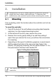

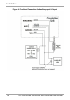
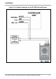
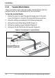

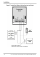
Table Of Contents
- 1. Introduction
- 2. Installation
- 3. Operation
- 4. Programming
- 4.1 Entering the Programming Mode
- 4.2 Exiting the Programming Mode
- 4.3 Changing the Open Code
- 4.4 Changing the Auxiliary Code
- 4.5 Changing the Programming Code
- 4.6 Changing the Normal/Secure Code
- 4.7 Changing the Normal/Bypass Code
- 4.8 Setting Fail Safe/Secure Operation, Tamper Siren and Lock Strike Release Time
- 4.9 Setting Auxiliary Modes
- 4.10 Keypad Heater Operation
- 4.11 Setting the Lockout Feature
- 4.12 Setting the Backlight Behavior
- 4.13 Enrolling Primary and Secondary Codes
- 4.14 Deleting Primary and Secondary Codes
- 4.15 Relay Codes Assignment
- 4.16 Changing PIN Code Length/Factory Default Settings
- 4.17 Replacing a Programming Code
- 4.18 Replacing a Normal/Secure Code
- 5. Technical Specifications

Installation
18 AC-Q4x Series Installation and Programming Manual
2.2.2 Terminal Block Models
These controllers come with removable terminal blocks that are
pushed on pins on the motherboard of the controllers.
To wire the terminal blocks:
1. Route the wires or cable through the large hole in the back
cover See Figure 6. Connect the terminal blocks as shown.
2. Wire the cabling according to the following diagrams.
3. Wiring the Lock Strike Relay & REX (Figure 7)
4. Wiring for Auxiliary Input & Output (Figure 8)
5. Wiring for the BL-D40 External Sounder (Figure 9)
Figure 6: Connections to Terminal Blocks