
Programming Manual
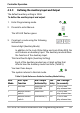
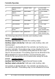
Table Of Contents
- 3.2.3.1 Keypad Transmission Formats
- 3.2.4.1 Proximity Card Transmission Formats
- 4.2.4.1 Changing from Normal Mode to Secure Mode
- 4.2.4.2 Changing from Secure Mode to Normal Mode
- 4.2.4.3 Changing from Normal Mode to Bypass Mode
- 4.2.4.4 Changing from Bypass Mode to Normal Mode
- 4.9.9.1 Auxiliary Mode 0
- 4.9.9.2 Auxiliary Mode 1
- 4.9.9.3 Auxiliary Mode 2
- 4.9.9.4 Auxiliary Mode 3
- 4.9.9.5 Auxiliary Mode 4
- 4.9.9.6 Auxiliary Mode 5
- 4.9.9.7 Auxiliary Mode 6
- 4.9.9.8 Auxiliary Mode 7
- 4.9.9.9 Auxiliary Mode 8
- 4.9.9.10 Auxiliary Mode 9
- 4.9.12.1 Primary Codes
- 4.9.12.2 Secondary Codes
- 4.9.12.3 Enrolling Methods
- 4.9.12.4 Enrolling Primary and Secondary Codes using Standard Method
- 4.9.12.5 Enrolling Secondary Codes using Search Method
- 4.9.13.1 Deleting Primary and Secondary Codes using Standard Method
- 4.9.13.2 Deleting Primary and Secondary Codes using Search Method
- 4.9.14.1 Relay Code Assignment using Standard Method
- 4.9.14.2 Relay Code Assignment using Search Method

Controller Operation
48 AYC-Ex5/T65 Series Installation and Programming Manual
• While in Secure mode when waiting for Secondary code.
Auxiliary input function: Red LED control
Auxiliary output activated by: Valid user code, Auxiliary code
For example, in Auxiliary Mode 9, the controller can function as a
2-door controller and also provide LED indicator functionality
control. The auxiliary relay is connected to the lock on the second
door. The auxiliary setting defines the Door Open time for the
second door. The auxiliary input is used to control the door
indicator (right LED). If the auxiliary input is open, the right LED
flashes red; if the auxiliary input is closed the right LED flashes
green.
4.9.10 Setting the Lockout Feature
If the controller is presented with wrong codes (PIN or card)
consecutively several times, the unit goes into Lockout mode.
When a lockout occurs, the controller keypad and reader are locked
so no codes can be entered until the set lockout period expires.
During Lockout, the left LED is Off, the right LED flashes red, and
the controller beeps every two seconds.
The default setting for the Lockout Feature is 4000 (Lockout
Disabled).
Using the lockout feature is highly recommended, especially
when selecting to use short PIN code length (4 or 5 digits).
To set the lockout feature:
1. Enter Programming mode.
2. Press 6 to enter Menu 6.
The left LED flashes green.
Green
Green
Green