FUNCTION C8 ENTER MENU ZONE 1 ZONE 2 ZONE 3 ZONE 4 C8 C8+ Eight Channel Power Amplifiers Amplificateurs de Puissance Huit Canaux Achtkanal-Endstufe Etapas de Potencia de Ocho Canales Achtkanaals vermogensversterkers Amplificatori finali a otto canali 8-kanals slutsteg 8-канальный усилитель мощности Owner’s Manual Manuel de l’utilisateur Bedienungsanleitung Manual de Instrucciones Gebruikershandleiding Manuale di istruzioni Instruktionsbok Инструкция пользователя BACK
C8 / C8+ Eight Channel Power Amplifiers 2 Important Safety Instructions Notice The RS232 connection should be handled by authorized persons only. WARNING: There are no user serviceable parts inside. Refer all servicing to qualified service personnel. WARNING: To reduce the risk of fire or electric shock, do not expose the unit to moisture or water. Do not expose the unit to dripping or splashing. Do not place objects filled with liquids, such as vases, on the unit.
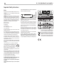
English 3 Figure 1-1: Controls and Connections Commandes et branchements Bedienelemente und Anschlüsse Controles y Conexiones 1 Bedieningselementen en aansluitingen Controlli e connessioni Kontroller och kontakter Органы управления и разъемы 2 3 4 FUNCTION C8 ENTER BACK MENU ZONE 1 ZONE 2 ZONE 3 ZONE 4 5 Button 1: Power7 Activate the unit or put it into standby mode. 8 RP-613B 2: ZONE 1 - 4 Configure the volume, source, bass treble and balance for Zone 1 to Zone 4 respectively.
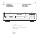
FUNCTION C8 C8 / C8+ Eight Channel Power Amplifiers ENTER 4 BACK MENU ZONE 1 ZONE 2 ZONE 3 ZONE 4 Figure 1-2: Controls and Connections Commandes et branchements Bedienelemente und Anschlüsse Controles y Conexiones 1 5 2 Bedieningselementen en aansluitingen Controlli e connessioni Kontroller och kontakter Органы управления и разъемы 83 7 4 RP-613B FUNCTION C8+ ENTER BRIDGED ZONE 1&2 ZONE ZONE 1 ZONE 2 1ZONE 3 ZONE 4 BRIDGED ZONE 3&4 ZONE 3 9 5 6 BACK MENU ZONE 2 ZONE 4 0 - = q 8
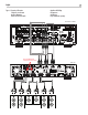
English 5 Figure 2: Connection Illustration Schéma de raccordement Anschlussdiagramm Ilustración del Conexionado Aansluiten Afbeelding Collegamento Anslutningar Подсоединение -пример Rotel RSP-1576MKII ON OFF PUSH PUSH Move the BRIDGE slide switches to the OFF position.
C8 / C8+ Eight Channel Power Amplifiers 6 Figure 3: Bridged Connection Illustration Schéma de raccordement pontée Abbildung der gebrückten Verbindung Ilustración del Conexionado en puente Overbrugde Aansluiten Afbeelding Collegamento a ponte Överbryggad Anslutningar Подсоединение мостового -пример Rotel RSP-1576MKII ON OFF PUSH PUSH Move the BRIDGE slide switches to the ON position.
English Important Notes When making connections be sure to: 4 Turn off all the components in the system before hooking up any components, including loudspeakers. 4 Turn off all components in the system before changing any of the connections to the system. It is also recommended that you: 4 Turn the volume control of the amplifier all the way down before the amplifier is turned on or off.
C8 / C8+ Eight Channel Power Amplifiers 8 Contents About Rotel Important Safety Instructions. . . . . . . . . . . . . . . . . . . . . . . . . . . . . . . . . . . . . . . . . . . 2 Figure 1-1: Controls and Connections 3 Figure 1-2: Controls and Connections 4 Figure 2: Connection Illustration 5 Figure 3: Bridged Connection Illustration 6 Important Notes 7 About Rotel. . . . . . . . . . . . . . . . . . . . . . . . . . . . . . . . . . . . . . . . . . . . . . . . . . . . . . . . 8 A Word About Watts. . . . .
English 9 operating together, Rotel is able to specify the true power output for all channels. components. Also avoid routing audio signal cables near power cords. This will minimize the chance it will pick up hum or interference. This can be important for your enjoyment, too. When watching movies, it’s nice to have the amplifier able to reproduce full power into all the channels at the same time, especially in the case of a volcano exploding! The unit generate heat as part of their normal operation.
C8 / C8+ Eight Channel Power Amplifiers 10 Power Switch and Power Indicator 1 Analog Inputs 8 12V Trigger Input and Output 0 For each pair of amplifier channels, connect the left channel output of your preamp to the LEFT INPUT on the amplifier. Connect the right channel of your preamp to the RIGHT INPUT. Make sure that the input A slide switch is in the STEREO position. The jack labeled OUT is for connecting another 3.5mm mono plug/cable to provide a 12 volt trigger signal to other components.
English 11 Polarity and Phasing The polarity – the positive/negative orientation of the connections – for every speaker and amplifier connection must be consistent so all the speakers will be in phase. If the polarity of one connection is reversed, bass output will be very weak and stereo imaging degraded. All wire is marked so you can identify the two conductors. There may be ribs or a stripe on the insulation of one conductor.
C8 / C8+ Eight Channel Power Amplifiers 12 •Z ONE NAME: The name of the Zones 1-4 can be customized. For example ZONE 1 can be named “AUDIO” for easier reference. Press the ENTER button to enter the zone name edit sub menu as below. The maximum zone name is limited to 6 characters. SOURCE: INPUT A, INPUT B, INPUT C, INPUT D. BASS: -10 ~ +10. Default: 0. TREBLE: -10 ~ +10. Default: 0. Name: -0123456789ABCD EFGHIJKLMNOPQRST UVWXYZ DEL DONE BALANCE: L10 ~ R10. Default: 0.
English be broadcast to all Zones 1- 4. The unit will resume the previous Source Input after approximately 10 seconds of no audio on the INPUT A source. Valid settings include: DISABLED (Default), ENABLED. •P A OVERRIDE VOL: This sets the volume level of ZONE 1 - 4 when the PA OVERRIDE function is activated. “45” is the factory default. Valid settings include: 0 ~ 96. Default: 45. 13 NOTE: Do NOT power off the unit during the software update process.
C8 / C8+ Eight Channel Power Amplifiers 14 Specifications C8 C8+ Max Power output 70 watts / channel Max Power output 150 watts / channel (8 channels driven, 4 ohms) (8 channels driven, 4 ohms) Continuous Power Output 50 watts / channel Continuous Power Output 100 watts / channel Total Harmonic Distortion Intermodulation Distortion (60 Hz : 7k Hz, 4:1) Frequency Response Line level Input Tone Control Bass Treble Damping Factor (20 Hz – 20k Hz, 8 ohms) Input Sensitivity / Impedance L
The Rotel Co. Ltd. Tachikawa Bldg. 1F., 2-11-4, Nakane, Meguro-ku, Tokyo, 152-0031 Japan Rotel USA Sumiko 11763 95th Avenue North Maple Grove, MN 55369 USA Phone: (510) 843-4500 (option 2) E-mail: Rotelsupport@sumikoaudio.net Rotel Canada Kevro International 902 McKay Rd. Suite 4 Pickering, ON L1W 3X8 Canada Tel: +1 905-428-2800 Rotel Europe Dale Road Worthing, West Sussex BN11 2BH England Phone: + 44 (0)1903 221 710 Fax: +44 (0)1903 221 525 www.rotel.