
Owner's Manual


11
English
Polarity and Phasing
The polarity – the positive/negative orientation of the connections – for every
speaker and amplier connection must be consistent so all the speakers will
be in phase. If the polarity of one connection is reversed, bass output will
be very weak and stereo imaging degraded. All wire is marked so you can
identify the two conductors. There may be ribs or a stripe on the insulation
of one conductor. The wire may have clear insulation with different color
conductors (copper and silver). There may be polarity indications printed
on the insulation. Identify the positive and negative conductors and be
consistent with every speaker and amplier connection.
Speaker Wire Connections
Turn off all the components in the system before connecting the speakers.
Route the wire from the unit to the speakers. Give yourself enough slack so
you can move the components to allow access to the speaker connectors.
For each group of channels, connect the left speaker to the pair of speaker
connectors labeled LEFT. Connect the right speaker to the speaker connectors
labeled RIGHT. Make sure that the positive terminal of the speaker is connected
to the + terminal on the unit. Make sure that the negative terminal of the
speaker is connected to the - terminal of the unit.
NOTE: Be sure there are no loose wire strands that could touch adjacent
wires or connectors.
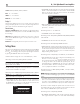
Plug connection
9
Connect the speaker wires as shown in the illustration. Insert the wire into
the opening and turn the screw to clamp the wire in place.
Be sure to keep the polarity of the connections correct. Speaker connectors
can be secured to the unit using the secure-locking screws on each side of
the connector. This will help prevent the connectors from falling out from
the socket.
R+
R--
L--
L+
Bridged Speaker Outputs Connection 5
See gure 3
Bridging allows 2 amplier channels to be connected providing higher
power for larger or more demanding speakers. To enable the bridging
function slide the BRIDGE ZONE 1&2 or BRIDGE ZONE 3&4 slide switch
5
to the ON position.
When bridged use the Left and Right input for Input A (Zone 1 and 2 bridged)
or the Input C (Zone 3 and 4 bridged).
Speaker output connections must follow the diagram found in Figure 3 to
ensure output power is properly wired from the unit to the speakers.
NOTE: Failure to following the bridging speaker wiring diagram will
result in inefcient output and will not properly bridge the amplier
channels together.
Network Connection -
The amplier can be attached to a network using the rear panel NETWORK
socket
-
. The NETWORK congurations allow both STATIC and DHCP IP
addressing. See the Network section of this manual under Setting Menu for
IP address conguration information.
The NETWORK connection allows software updates to be downloaded from
the Internet. The NETWORK connection also allows IP control for integration
with automation systems.
For additional information on the IP control please contact your authorized
Rotel dealer.
RS232 Connector =
The unit can be controlled via RS232 for integration with automation systems.
The RS232 input accepts a standard STRAIGHT DB-9 Male-to-Female cable.
For additional information on the connections, software, and operating codes
for RS232 control of the amplier, contact your authorized Rotel dealer.
Cooling Fans
The amplier includes 2 cooling fans to help exhaust the heat generated
by the power supply and amplier modules. These fans will operate when
internal thermostat sensors detect cooling is required. The fan speed with
increase as needed when the unit temperature increases as detected by
the internal sensors.
NOTE: If the cooling fans and cooling tunnels require cleaning please
contact your authorized Rotel dealer for more information.
Front Panel Overview
The following is a brief overview of the controls and features on the front
panel of the unit.
ZONE 1-4
2
The unit can control the volume, source, bass treble and balance for Zone 1
to Zone 4 respectively. Press the ZONE 1 - 4 buttons to toggle between the
menus and use the / /‹/› arrow buttons to change the value. Press and
hold any ZONE 1 - 4 buttons can mute the source from the corresponding
ZONE 1 - 4.
VOLUME: 0 ~ 96. Default: 45.