
Owner`s manual


6
SPEAKER SELECTOR RSS-900
Associated Components
The RSS-900 is designed for use with amplifiers that can produce
as much as 200 watts per channel. (See the information in the fol-
lowing section regarding ventilation.) The amplifier should be ca-
pable of handling 4 ohm impedance loads.
NOTE: If speakers that have a minimum impedance of less than 4
ohms are connected to the RSS-900 the impedance the amplifiers
receives may be less than 4 ohms. Check the instruction manual
for your speakers for this information. If you are unsure about
whether or not a certain combination of speakers can safely be
used with the RSS-900 and your amplifier consult your authorized
Rotel dealer.
Placement
Place the RSS-900 on a firm flat surface where it will be free from
excessive dust, heat or cold, moisture or high humidity, or expo-
sure to direct sunlight. Do not allow any foreign objects to fall into
the ventilation holes of the RSS-900.
Like many audio components that handle high-level signals, the
RSS-900 produces some heat during normal operation. Do not
place anything on top of the RSS-900 or allow the vent holes in the
top of the cabinet to be blocked. There should be at least 3”
(75mm) of room above the RSS-900 to allow for heat dissipation.
Cables
Because as many as 6 pairs of speakers may be connected to the
outputs of the RSS-900, the wires from the amplifier output to
RSS-900 input should be heavy gauge (12 AWG) speaker wire.
Slightly lighter gauge wire may be used to connect the RSS-900 to
the speakers. High quality, high performance wire will frequently
improve the sound of a system. Consult your authorized Rotel
dealer for advice about the best wires to use with your system.
Connection
Note: Turn off the power to all the components in the system be-
fore you make any signal connections.
Polarity/Phasing and Proper Channel Connection
The polarity — the positive/negative orientation — for every con-
nection between the amplifier and the RSS-900, and between the
RSS-900 and the speakers, must be consistent so all the speakers
will be in phase. If the polarity of one connection is mistakenly re-
versed, bass output will be very weak and stereo imaging de-
graded. All wire is marked so you can identify the two conductors.
There may be ribs or a stripe on the insulation of one conductor.
The wire may have clear insulation with different color conduc-
tors (copper and silver). There may be polarity indications printed
on the insulation. Identify the positive and negative conductors
and be consistent with every connection.
Note: All speaker wire consists of many small strands of wire.
When making connections to the terminals of the amplifier, the
RSS-900, or the speakers, twist these strands into a tight bundle
and secure all the wires in the terminal. There must not be any
loose strands of wire from one terminal that could touch the other.
This will cause a short circuit.
It is also very important to be sure that the left and right channels
do not get reversed. Work carefully and be sure that the proper
channels are connected at every amplifier, RSS-900 and speaker
connection point.
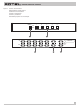
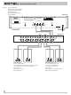
Input From Amplifier
3
(See the connection diagram Figure 2)
Use heavy duty speaker wires to connect the output of the ampli-
fier to the input of the RSS-900 as shown.
Direct Speaker Output Connection
4
Connect the speakers in your primary listening location to the out-
put terminals labeled “Direct”. These outputs do not have the im-
pedance matching and capacitance control components that the
other outputs (1-5) have. This provides you with the convenience
of being able to turn the main speakers in your system on and off,
while ensuring that the signal to them is not affected by extra cir-
cuitry.
Speaker Output Connections 1 – 5
5
Connect the secondary speakers in your system to the outputs la-
beled 1 through 5. These outputs have impedance matching and
capacitance control components that allow the amplifier to safely
drive any combination of speakers.