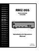
RMZ-955 MULTI-ROOM SYSTEM MULTI-ZONE CUSTOM CONTROLLER RMZ-955 DIGITALLY CONTROLLED AUDIO PROCESSING POWER POWER ZONE A ACTIVE ACTIVE CODE ZONE B ACTIVE ACTIVE CODE ZONE C ACTIVE CODE ZONE D ACTIVE CODE I.R.
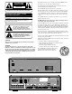
Read all the instructions before connecting or operating the RMZ-955 . Keep this manual so you can refer to these safety instructions. MULTI-ROOM SYSTEM CONTROLLER RMZ-955 CAUTION RISK OF ELECTRIC SHOCK DO NOT OPEN Heed all warnings and safety information in these instructions and on the product itself. Follow all operating instructions. Clean the RMZ-955 only with a dry cloth or a vacuum cleaner. CAUTION: TO REDUCE THE RISK OF ELECTRIC SHOCK, DO NOT REMOVE COVER. NO USER-SERVICEABLE PARTS INSIDE.
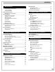
CONTENTS Getting Started 4 Controlling the Remote Zones System Flexibility System Highlights Component Description _______________________________ RMZ-955 Controller/Amplifier System Planning _____________________________________ RR-952 IR Remote Control RSM-901 Sensor/Display RKP-901 Keypad RSM-901/RKP-901 Combination Placement Connections: IR Flood Emitter IR Repeater Jacks System Wiring Considerations ________________________ Data Cable and Connectors Speaker Cables Zone Configuration ________________
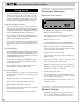
MULTI-ROOM SYSTEM CONTROLLER RMZ-955 ○ ○ ○ ○ ○ ○ ○ ○ ○ ○ ○ ○ ○ ○ ○ ○ ○ ○ ○ ○ ○ ○ ○ ○ ○ ○ ○ ○ ○ ○ ○ ○ Getting Started The Rotel RMZ-955 Multi-Room Control System distributes audio signals from a single set of source components to as many as four separately controlled remote zones or listening areas. The centrally located RMZ-955 controller/amplifier contains source selection, microprocessor controlled communications circuitry and independent preamplifier/power amplifiers for all zones.
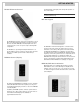
GETTING STARTED RR-952 IR Remote Control You’ll find details of the display in the Set Up and Operation sections of this manual. NOTE: An RSM-901 connected to the Zone A data input MUST be used during initial set-up. RKP-901 Keypad The RR-952 infrared remote control serves a dual purpose. In addition to providing dedicated pushbuttons for the most needed functions of both the RMZ-955 controller/amplifier and source components, it also serves as a quick set-up tool during initial configuration.
MULTI-ROOM SYSTEM CONTROLLER RMZ-955 tions which allow linking additional RMZ-955 controllers for large systems. Depending on the design of the associated components, these pass-through source connections may alternatively be used to “share” source components with a separate home theater or audio system. If the RMZ-955 is on an open shelf, the emitter’s signal must first travel to an IR-reflective surface (an opposing wall, for example) and then to the source component.
GETTING STARTED Speaker Cables Unshielded two conductor 18 gauge (AWG) speaker wire is the minimum acceptable standard for connections between the RMZ-955 controller/ amplifier and zone loudspeakers. Particularly long runs may call for use of heavier wire. ○ ○ ○ ○ ○ ○ ○ ○ ○ ○ ○ ○ ○ ○ ○ ○ ○ ○ ○ ○ Zone Configuration AM/FM Tuner CD Player Basic Zone Complement Each remote zone must include at least one control device and a pair of loudspeakers.
MULTI-ROOM SYSTEM CONTROLLER RMZ-955 Installation: RMZ-955 Controller This section covers all hardware installation and configuration issues related to the RMZ-955 controller, including wiring connections for AC power, source connections, speaker connections, pre-amp connections, data cable connections to the remote zones, Infrared control connections, and special features such as the paging feature.
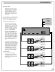
INSTALLATION: RMZ-955 CONTROLLER ○ ○ ○ ○ ○ ○ ○ ○ ○ ○ ○ ○ ○ ○ ○ ○ ○ ○ ○ ○ ○ ○ ○ ○ ○ ○ ○ ○ ○ ○ ○ ○ Note 1: The RMZ-955 does not accept a phono cartridge’s output directly. If required, use a separate phono preamp (such as Rotel’s RQ-970BX) to boost phono signal to line level. Source connections The RMZ-955 has four pair of RCA inputs for four source components, as well as four pair of RCA “loop-through” outputs that can send the source signals to other components.
MULTI-ROOM SYSTEM CONTROLLER RMZ-955 LLER D EU TRO PM N O IM 5 MC RM INU E K STO MZ-95430W A M R SPE 4 OH NO.
INSTALLATION: RMZ-955 CONTROLLER The long runs from amplifier to speaker typically found in multizone installations demand heavy gauge, low resistance speaker wire. Small diameter wire reduces effective amplifier power and adds substantial distortion to the audio signal.
MULTI-ROOM SYSTEM CONTROLLER RMZ-955 ○ ○ ○ ○ ○ ○ ○ ○ ○ ○ ○ ○ ○ ○ ○ ○ ○ ○ ○ ○ ○ ○ ○ ○ ○ ○ ○ ○ ○ ○ ○ ○ Data cable connections Data communication to and from the RMZ-955 controller and the remote zones’ RSM-901 sensor/displays and RKP-901 keypads is by 6 conductor shielded cable. Note: One, and only one, data cable runs from the RMZ-955 to each zone.
INSTALLATION: RMZ-955 CONTROLLER ○ ○ ○ ○ ○ ○ ○ ○ ○ ○ ○ ○ ○ ○ ○ ○ ○ ○ ○ ○ ○ ○ ○ ○ ○ ○ ○ ○ ○ ○ ○ ○ Infrared Control System The RMZ-955’s IR system provides extensive control flexibility accepting remote control codes generated by keypads and/or hand-held remotes, relaying them to the system controller, and passing them along to the source components via a front-panel flood emitter or individual remote IR emitters plugged into the rear panel.
MULTI-ROOM SYSTEM CONTROLLER RMZ-955 ○ ○ ○ ○ ○ ○ ○ ○ ○ ○ ○ ○ ○ ○ ○ ○ ○ ○ ○ ○ ○ ○ ○ ○ ○ ○ ○ ○ ○ ○ ○ ○ Paging Input The paging input allows announcements to be made over the system, and, if required, for Zones to be momentarily muted, in conjunction with a doorbell or a phone system. The paging feature needs to be activated from an external source via the “paging trigger” RCA-type input jack on the back of the RMZ-955.
INSTALLATION: ZONE CONTROL DEVICES RSM-901 Mounting Installation: Zone Control Devices The RSM-901 Sensor/Display mounts in a single-width wall box or in a double width box with the RKP-901 keypad.
MULTI-ROOM SYSTEM CONTROLLER RMZ-955 RSM-901 Data Connections Zone Configuration Prepare the data cable with the supplied termination plug using the same color coding as previously described for the RMZ-955. ON DIP SWITCH See instructions for configuration settings 1 2 3 4 5 6 OFF RESET SWITCH SW1 Press after changing configuration Each RSM-901 must be configured or “addressed” as being in Zone A, Zone B, Zone C, or Zone D.
INSTALLATION: ZONE CONTROL DEVICES System Reset After changing any of the above configurations, reset the RSM-901 by pressing the RESET switch (SW1). This is essential to allow the new setting to take effect. RECEIVE Source Component Set-up After installation, refer to System Set-up and Programming (page 21) for configuring the proper data codes for source component operation.
MULTI-ROOM SYSTEM CONTROLLER RMZ-955 ○ ○ ○ ○ ○ ○ ○ ○ ○ ○ ○ ○ ○ ○ ○ ○ ○ ○ ○ ○ ○ ○ ○ ○ ○ ○ ○ ○ ○ ○ ○ ○ Zone Connection Strategies Each zone will support up to three RSM-901s and three RKP-901s. All of the command devices for one zone should connect to each other in serial fashion using their appropriate circuit board-mounted “In” and “Out” terminals. Each RSM-901 signals when it receives and processes a command. This happens regardless of whether the command was generated by a keypad or a hand held remote.
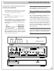
INSTALLATION: MULTI-CONTROLLER SYSTEMS Optional +5V external trigger RMZ-955 "C" ~ UNSWITCHED CAUTION SWITCHED LINK IN LINK OUT AC120V PAGING WARNING:TO REDUCE THE RISK OF FIRE OR ELECTRICAL SHOCK DO NOT EXPOSE THIS EQUIPMENT TO RAIN OR MOISTURE. RISK OF ELECTRIC SHOCK DO NOT OPEN MULTI-ZONE CUSTOM CONTROLLER MODEL NO.
MULTI-ROOM SYSTEM CONTROLLER RMZ-955 ○ ○ ○ ○ ○ ○ ○ ○ ○ ○ ○ ○ ○ ○ ○ ○ ○ ○ ○ ○ ○ ○ ○ ○ ○ ○ ○ ○ ○ ○ ○ ○ AC Power Multiple controller systems require handling AC connections in a way that allows any zone to “power up” or “power down” the system. In other words, there must be a provision for zones connected to additional RMZ-955 controllers to control the system’s switched AC outlets.
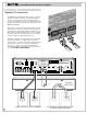
INSTALLATION: MULTI-CONTROLLER SYSTEMS Then, using standard shielded RCA-RCA audio interconnet cables, connect Source 1’s “loop through” outputs on the first RMZ-955 “A” to the corresponding Source 1 inputs on the second RMZ-955 “B”. Repeat this procedure for all four sources. If a system requires a third RMZ-955, repeat this procedure but, this time, connect the “loop-though” source output on the second RMZ-955 “B” to the corresponding input on the third RMZ-955 “C” and so for a fourth controller “D”.
MULTI-ROOM SYSTEM CONTROLLER RMZ-955 For 4 RMZ-955s (13-16 zones): • Remove the jumpers between terminals 2 and 3 of the TX FORMAT blocks on RMZ-955 “B” and “C” and “D” to disable their flood emitters. Leave the jumper in place on the first RMZ-955 “A” to use its front-panel flood emitter. Remove this jumper to disable the flood emitter when using back panel IR repeaters. • Connect terminal 3 of the RMZ-955 “D” TX FORMAT block to terminal 4 on RMZ-955 “C”.
INSTALLATION: MULTI-CONTROLLER SYSTEMS ○ ○ ○ ○ ○ ○ ○ ○ ○ ○ ○ ○ ○ ○ ○ ○ ○ ○ ○ ○ ○ ○ ○ ○ ○ ○ ○ ○ ○ ○ ○ ○ Notes on multi-controller set-up Power Toggle Set-up We recommend in systems with multiple RMZ-955 controllers (with full AC control from any Zone) that you select source components that do not require a “power toggle” command, i.e. components that fully power up when AC power is applied, instead of going into a standby mode.
MULTI-ROOM SYSTEM CONTROLLER RMZ-955 System Set-up & Programming ○ ○ ○ ○ ○ ○ ○ ○ ○ ○ ○ ○ ○ ○ ○ ○ ○ ○ ○ ○ ○ ○ ○ ○ ○ ○ ○ ○ ○ ○ ○ ○ Source Commands The RMZ-955 is factory set for use with Rotel source components, including Rotel multi-disc CD players. No adjustments are necessary for these components. b) Select an input (Tuner, CD, Tape/Sat, or VCR/DVD) on the RR-952 so that the corresponding label shows on Zone A’s RSM-901 sensor/display. c) Place the Set-up Card over the RR-952’s pushbuttons.
SYSTEM SET-UP & PROGRAMMING e) Push the desired command code button for the component you want to change. The available choices for that input are grouped together on the Set Up Card.
MULTI-ROOM SYSTEM CONTROLLER RMZ-955 ○ ○ ○ ○ ○ ○ ○ ○ ○ ○ ○ ○ ○ ○ ○ ○ ○ ○ ○ ○ ○ ○ ○ ○ ○ ○ ○ ○ ○ ○ ○ ○ Operating Instructions RR-952 Hand-held Remote As detailed in above, the RMZ-955 should ALWAYS be plugged into an uninterruptable AC source. This ensures that essential RMZ-955 system benefits such as remote controlled zone activation and source selection are always available.
OPERATING INSTRUCTIONS CD control buttons Mute RANDOM: This instructs the CD player to play tracks (and discs for multi-disc changer) in whatever random order the CD player chooses. DISC: This advances the CD player to the next available disc. (functional only with multi-play CD players) This temporarily reduces zone volume to very quiet levels for telephone conversations, etc. Press Mute again to restore original volume settings.
MULTI-ROOM SYSTEM CONTROLLER RMZ-955 ○ ○ ○ ○ ○ ○ ○ ○ ○ ○ ○ ○ ○ ○ ○ ○ ○ ○ ○ ○ ○ ○ ○ ○ ○ ○ ○ ○ ○ ○ ○ ○ ○ you hear a different source, sending a Play command if necessary. Finally, the Input Select button can be used as a Play button to resume operation following a previous Pause command. RKP-901 Keypad The details are not important. If you want to hear a source in your room, just press the Input Select button for that source and the system will worry about the details for you.
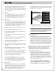
OPERATING INSTRUCTIONS ○ ○ ○ ○ ○ ○ ○ ○ ○ ○ ○ ○ ○ ○ ○ ○ ○ ○ ○ ○ ○ ○ ○ ○ ○ ○ ○ ○ ○ ○ ○ ○ RSM-901 Sensor/Display The dot matrix display shows the following status information: The RSM-901 sensor/display receives IR signals from the RR-952 hand held controller and other IR devices. It also provides feedback on system status through a dot matrix LED display and indicators. In addition, it provides convenience features including a time of day display and a “wake to music” alarm clock function.
MULTI-ROOM SYSTEM CONTROLLER RMZ-955 Volume Level: When the Volume setting is changed in the Zone, the RSM-901 will momentarily display the new setting: a) Turning Alarm ON or OFF: Press the MIN button to activate the wake-up alarm. Press the HOUR button to deactivate. The ALARM LED reminds you that the alarm has been activated. When finished, press the MODE button to record your changes and advance to the next step.
OPERATING INSTRUCTIONS c) Select the Default Source: Select the source component that you want to begin playing when the alarm goes off. Press the HOUR button to select the TUNER. Press the MINUTE button to select the CD (make sure there is a disc in the player). When finished, press the MODE button to record your changes and advance to the next step.
MULTI-ROOM SYSTEM CONTROLLER RMZ-955 RMZ-955 MULTI-ROOM SYSTEM The Rotel Co., Ltd. 10-10 Shinsen-Cho Meguro-Ku Tokyo 150, Japan Phone: +81-3-5458-5325 Fax: +81-3-5458-5310 Rotel of America 54 Concord Street North Reading, MA 01864-2699 Phone: 978-664-3820 Fax: 978-664-4109 Rotel Deutschland Kleine Heide 12 D-33790 Halle/Westf., Germany Phone: 05201-87170 Fax: 05201-73370 Printed in the USA.