
Owner`s manual


8
RB-1592 Stereo Power Amplifier
OFF cuts power to the amplifier, regardless of whether or not a
trigger signal is present.
12V Trigger Input
8
An input jack for connecting the wires carrying a +12 volt trigger
signal from a Rotel preamp or surround sound processor to turn the
amplifier on and off. To use this feature the adjacent flip switch must
be set to the ON position (see previous section). The TRIGGER INPUT
accepts any control signal (AC or DC) ranging from 3 volts to 30 volts.
Use a cable with mono 3.5 mm mini-plugs on both ends. The +12V
DC signal appears at the “tip” connector.
12V Trigger Output
8
The 12V Trigger jack labeled OUT is used to pass the remote turn-
on signal to a second Rotel amplifier. Any 12V Trigger signal at the
INPUT jack will be passed through to the OUT jack.
Signal Connections
The RB-1592 provides two types of input connections — unbalanced
RCA type connections as found on nearly all audio equipment as well
as balanced XLR connections..
RCA Inputs
3
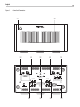
See figure 2
There is one RCA input for each of the two amplifier channels. These
RCA inputs accept audio signals from pre-amplifiers or surround
sound processors. Use high quality audio interconnect cables for best
performance.
XLR Inputs
4
See figure 2
There is one XLR input for each of the two amplifier channels. These
XLR inputs accept audio signals from preamplifiers or surround sound
processors with XLR outputs.
Input Selector Switch
5
A toggle switch in the middle of the RB-1592 rear panel selects the
type of input signal to use. Select the correct inputs to use with this flip
switch.
Note: To prevent loud, potentially damaging noises, make sure the
amplifier is turned off when you make any singal connections..
Connect the left channel output of your preamp to the LEFT INPUT on
the RB-1592. Connect the right channel of your preamp to the RIGHT
INPUT.
Speakers
See Figure 2
The RB-1592 has four pairs of color coded binding posts, two for each
channel. These connectors accept bare wire, connector lugs, or dual
banana type connectors (except in the European Community countries
where their use is not permitted).
Speaker Selection
The nominal impedance of the loudspeaker(s) connected to the RB-
1592 should be a minimum of 4 ohms. When driving multiple pairs of
speakers connected in parallel, the effective impedance the amplifier
sees is cut in half. For example, when driving two pair of 8 ohm
speakers, the amplifier sees a 4 ohm load. When driving multiple
speakers in parallel, select speakers with a nominal impedance of 8
ohms or higher.
Speaker Wire Selection
Use insulated two-conductor stranded wire to connect the RB-1592 to
the speakers. The size and quality of the wire can have an audible
effect on the performance of the system. Standard speaker wire will
work, but can result in lower output or diminished bass response,
particularly over longer distances. In general, heavier wire will
improve the sound. For best performance, you may want to consider
special high-quality speaker cables. Your authorized Rotel dealer can
help in the selection of cables for your system.
Polarity and Phasing
The polarity or positive/negative orientation of the connections for
every speaker and amplifier connection must be consistent so all
the speakers will be in phase. If the polarity of one connection is
mistakenly reversed, bass output will be very weak and stereo imaging
degraded. All wire is marked so you can identify the two conductors.
There may be ribs or a stripe on the insulation of one conductor. The
wire may have clear insulation with different color conductors (copper
and silver). There may be polarity indications printed on the insulation.
Identify the positive and negative conductors and be consistent with
every speaker and amplifier connection.
Speaker Wire Connection
6
See Figure 2
Route the wires from the RB-1592 to the speakers. Give yourself
enough slack so you can move the components to allow access to the
speaker connectors.
If you are using dual banana plugs, connect them to the wires and
then plug into the backs of the binding posts. The binding posts
should be screwed in all the way (clockwise).
If you are using terminal lugs, connect them to the wires. If you
are attaching bare wires directly to the binding posts, separate the
wire conductors and strip back the insulation from the end of each
conductor. Be careful not to cut into the wire strands. Unscrew (turn
counterclockwise) the binding post. Place the connector lug or wire
around the binding post shaft. Turn the binding post clockwise to
clamp the connector lug or wire firmly in place.